Band Pass Filter
Filters are circuits that remove part of a complex AC signal.
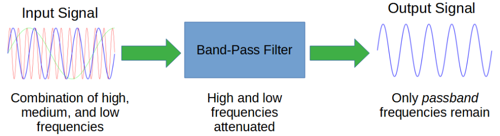
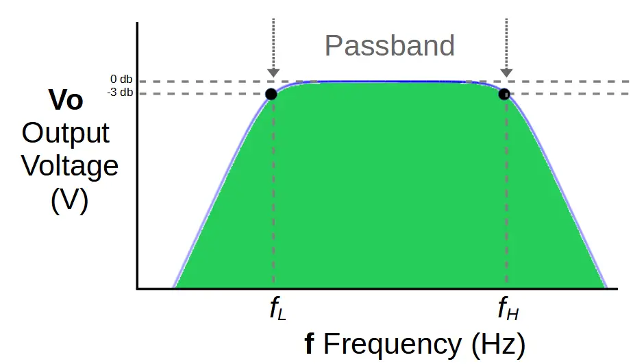
A band pass filter removes frequencies above and below a designated band of frequencies called a passband. The band pass filter attenuates the frequencies around the band and outputs only the passband.
The process of removing unwanted frequencies is called attenuation. A band pass filter primarily attenuates high frequencies so that the resulting output is comprised of only frequencies within the passband.
Like other filters, band pass filters don’t create the frequencies they output; they simply eliminate frequencies around the passband.
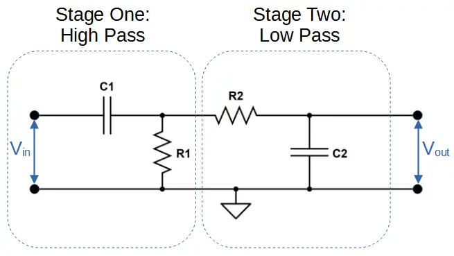
Band-pass filters are created by combining a high pass filter and a low pass filter in series.
The high pass filter attenuates frequencies above the passband, and the low pass filter attenuates frequencies below the passband.
The passband is created by using a high pass filter that has a cut-off frequency fL at the bottom of the passband, and a low pass filter with a cut-off frequency fH at the top of the passband.
How a Band Pass Filter Works
Band pass filters are known as 2nd stage filters because they employ two sub-filter circuits, performing the total filtering ‘action’ in two stages.
The first stage is the high pass filter. This forms the lowest point of the passband and is marked by the cut-off frequency of this filter, fL. The high pass filter allows all frequencies to pass that are higher than fL and attenuates the frequencies below fL.
The second stage is the low pass filter. This forms the highest point of the passband and is marked by it’s own cut-off frequency fH. The low pass filter allows all frequencies to pass that are lower than fH and attenuates the frequencies above fH.
The two filter stages are cascaded together, which means that the output of one must pass through the other.
The low and high pass filter stages each use a combination of a resistor and capacitor in order to function, but use different configurations that allow them both to make use of capacitive reactance.
Capacitive Reactance
Both filters rely on the concept of capacitive reactance in order to function.
Capacitive reactance (abbreviated XC) is a frequency dependent term, and determines the voltage drop across the capacitor.
The following equation expresses capacitive reactance as a function of both frequency (f) and capacitance (C):
X_C = \frac{1}{\omega C} = \frac{1}{2\pi fC}Omega (ω) is the angular frequency, and is used to simplify the formula. The angular frequency (ω) is equal to 2 times π times the frequency of the AC signal. It’s also equal to 2π over the period, T:
\omega=2\pi f=\frac{2\pi}{T}The capacitive reactance is inversely proportional to the frequency.
This means that a high frequency will result in a low capacitive reactance, and the signal will pass through the capacitor relatively unhindered. A low frequency will be effectively blocked, with a large voltage across the capacitor at low frequencies.

A high pass filter makes use of this phenomenon by taking its’ output through the capacitor, while a low pass filter takes its output across the capacitor. This simple configurational difference is what allows each filter to work.
The band-pass filter makes use of both in order to achieve an output of a selected frequency passband.
Band Pass Stage One: High Pass Filter
The first stage of the band pass filter is the high pass filter.
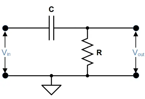
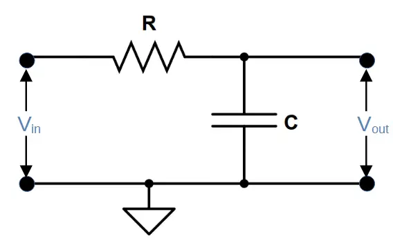
High pass filters feature a capacitor and resistor in series. The capacitor produces a capacitive reactance that is low at high frequencies and high at low frequencies. Low frequencies in the signal are attenuated when they encounter the capacitor. The output is taken across the resistor.
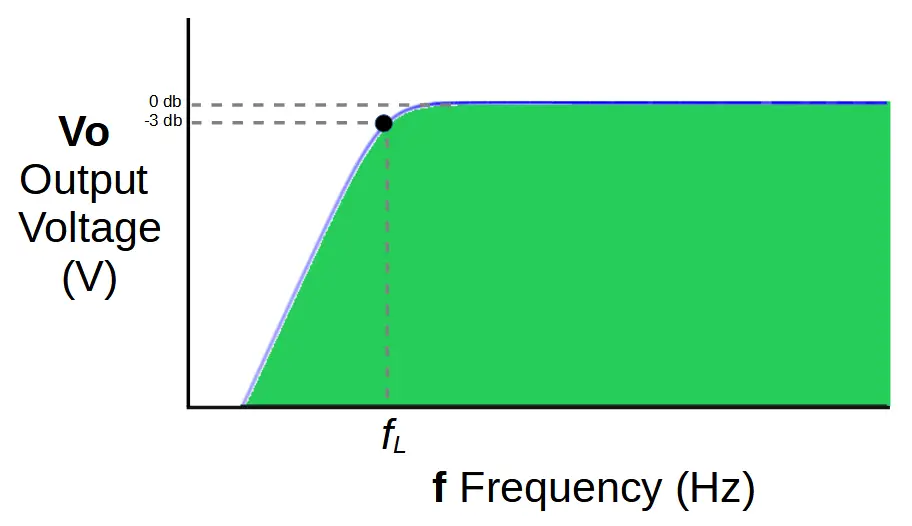
Frequencies below the passband are thereby attenuated by using a high pass filter with a cut-off frequency of fL.
The cut-off frequency fL represents a voltage drop of -3db, or 70.7% of the input signal.
Below fL the signal strength declines rapidly.
The cut-off frequency fL is determined by the values of resistor R1 and capacitor C1 in the circuit.
f_L = \frac{1}{2 \pi R_1 C_1}Band Pass Stage Two: Low Pass Filter
The first stage of the band pass filter is the low pass filter.
Like high pass filters, low pass filters also feature a resistor and capacitor in series. However in the low pass filter, the output is taken across the resistor rather than the capacitor. This allows the circuit a high output when the capacitive reactance is high.
As a result, frequencies above the passband are attenuated by using a low pass filter with a cut-off frequency of fH.
When this output is combined with that of the high-pass filter, a passband is generated between fL and fH.
This is the final output of the band pass filter.
The cut-off frequency fH is determined by the values of resistor R2 and capacitor C2 in the circuit.
f_H = \frac{1}{2 \pi R_2 C_2}Cascading the High and Low Pass Filters
In order for the band pass filter to function, the two filters must be cascaded together.
Cascading occurs when the output of the high pass filter is connected to the input of the low pass filter.
The complete circuit therefore allows the high pass filter to attenuate frequencies below fL, and then allows the low pass filter to attenuate frequencies above fH.
Bandwidth
Band pass filters introduce the concept of bandwidth, which is the size of the passband in hertz. Mathematically, bandwidth is defined as the difference between fH and fL:
Bandwidth = fH – fL
A filter with a wider bandwidth therefore allows more frequencies than a filter with a smaller bandwidth.
Resonant Frequency of Band Pass Filter
Band pass filters have a specific resonant, or center, frequency at which their output is greatest. The resonant frequency is abbreviated fr and can be found by taking the square root of the high and low cut-off frequencies:
f_r = \sqrt{f_L \times f_H}Recall that ƒL is the -3dB cut-off frequency from the high-pass filter stage, and ƒH is the upper -3db cut-off frequency from the low-pass filter stage.
Ideal vs. Actual Band Pass Filters
In this tutorial, we have discussed ideal band pass filters and it is important to realize that real-life band pass filters have important limiting factors.
The most important of these limitations is the fact that the coupled high and low pass filters will influence each other; the reactance will not remain the same as in the ideal case.
The easiest way to overcome this issue is to use an amplifier after each filter stage. An amplifier such as an operational amplifier (op-amp) will allow each stage to function without affecting the other. Since most signals require amplification for an ideal output, this solution allows the circuit designer to make use of a component that would already likely be used in order to allow the filter to function better.
Summary of Band-Pass Filters
We have seen that band pass filters are a type of 2nd order filter that make use of both high and low pass filter circuits in order to function.
By cascading the filters, the output is passed from one filter stage to the next, allowing a more complex output in the form of the passband.