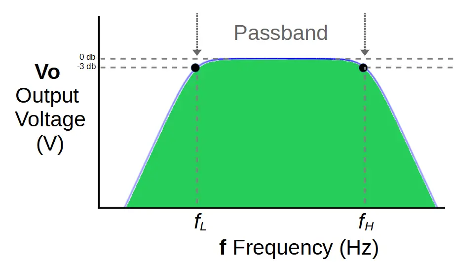
The band pass filter is a type of filter circuit that is used to attenuate frequencies above and below a designated band of frequencies called a passband.
This page contains a series of calculators to aid in the design of band pass filter circuits.
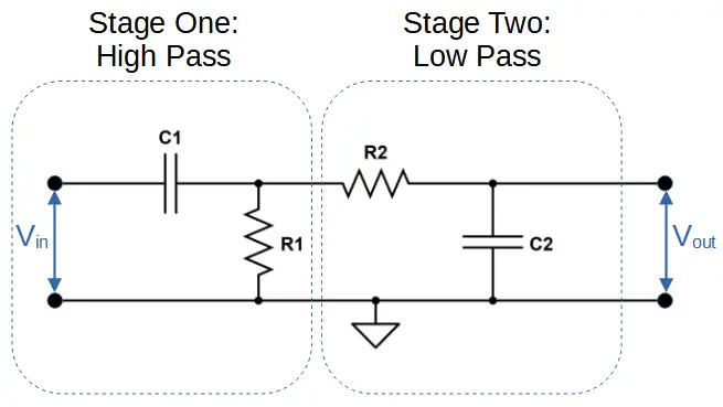
The band pass filter consists of a high pass filter and low pass filter cascaded in series.
Band pass filters contain four basic components that are used to determine the passband.
Band Pass Filter Circuit
Band pass filters output a passband that is determined by two characteristic frequencies: the low cut-off frequency FL and the high cut-off frequency FH. These frequencies are determined by the values of the components used.
The components of the high-pass filter stage, C1 and R1, determine the value of the low cut-off frequency FL.
The components of the low-pass filter stage, C2 and R2, determine the value of the high cut-off frequency FH.
This page contains a series of calculators to help you design and understand the band pass filter circuit.
It features calculators for the characteristic cut-off frequencies, values of the capacitors and resistors, and a resonant frequency calculator.
Band Pass Filter Cut-Off Frequency Calculator
The band pass filter cut-off frequency calculator can be used to calculate the cut-off frequencies of the filter. Two inputs are required for each cut-off frequency.
Calculation of the low cut-off frequency FL requires (1) the resistance of R1, and (2) the capacitance of C1. Calculation of the high cut-off frequency FH requires (1) the resistance of R2, and (2) the capacitance of C2. Based on these values, the calculator will provide the cut-off frequency as well as the resonant frequency of the filter.
The following equations determine FL and FH in the band-pass filter:
f_L = \frac{1}{2 \pi R_1 C_1}f_H = \frac{1}{2 \pi R_2 C_2}Band Pass Filter Capacitor Selection Calculator
The band pass filter capacitor calculator can be used to calculate the values of capacitors needed to create a filter with a specific cut-off frequencies FL and FH.
Calculation of each capacitor value requires two inputs. C1 requires the low cut-off frequency FL and the resistance of R1. C2 requires the high cut-off frequency FH and the resistance of R2.
The following equations determine C1 and C2 in the band-pass filter:
C_1 = \frac{1}{2 \pi R_1 F_L}C_2 = \frac{1}{2 \pi R_2 F_H}Band Pass Filter Resistor Selection Calculator
The band pass filter resistor calculator can be used to calculate the values of resistors needed to create a filter with a specific cut-off frequencies FL and FH.
Calculation of each resistor value requires two inputs. R1 requires the low cut-off frequency FL and the capacitance of C1. R2 requires the high cut-off frequency FH and the capacitance of C2.
The following equations determine R1 and R2 in the band-pass filter:
R_1 = \frac{1}{2 \pi C_1 F_L}R_2 = \frac{1}{2 \pi C_2 F_H}Band Pass Filter Resonant Frequency Calculator
The band pass filter resonant frequency calculator can be used to determine the resonant, or center, frequency of a filter with cut-off frequencies FL and FH.
Calculation of the resonant frequencies requires both the low cut-off frequency FL and high cut-off frequency FH.
If these calculators didn’t help, check out our other calculators for electronics or our comprehensive tutorials!