Clipper Circuits
Clipper circuits are a type of electronic circuit that is used to reduce the amplitude of an analog signal. Clipper circuits help limit distortion and noise in digital signals by clipping off any sudden waveform peaks above or below a certain threshold level.
Clipper circuits use a combination of resistors and diodes in order to modify a signal by ‘clipping’, or flattening, the top or bottom (or both) of a waveform. There are also clipper circuits based on Zener diodes, which are used to clip both sides of a waveform simultaneously.
In this article, we’ll discuss what clippers are and how they work. We will also cover the different types of clippers so you know which one is right for your application. Finally, we will discuss some tips on using clipper circuits properly so you get the best performance possible!
What Are Clipper circuits?
Clipper circuits are a type of electrical circuit that is used to limit the amplitude of a signal delivered to an output. Clipper circuits can be used in both digital and analog applications.
There are many different types of clipper circuits but they are all based on the similar principle of using a diode to provide a reference voltage drop. In this way, when current flows through the diode, a reference voltage across the diode is established. But when current is shorted around the diode, the current is only limited by the resistor, allowing the waveform to pass unclipped.
Types of Clipper Circuits
Clippers can be classified in several ways:
- Shunt (parallel) vs. series clippers.
- Unbiased vs. biased clippers.
- Diode vs. Zener diode clippers.
Shunt (parallel) vs. series clippers
Defines whether the diode is in parallel or series with the load.
Performance of the clipper circuit can be affected by the frequency of the AC signal used. High frequency signals tend to be attenuated by the diode capacitance in the clipper, giving the clipper attributes similar to a low-pass filter.
Similarly, the series clipper can function like a high-pass filter as high frequencies can travel through the diode without being sufficiently blocked, thereby reducing the effectiveness.
Shunt clippers also offer the additional dual/combination clipper circuit configuration in which both the positive and negative half-cycles of the waveform are clipper. This functionality is not possible with a series configuration, as two opposing diodes in series would effectively block all current in both directions.
Unbiased vs. biased clippers
Defines whether a voltage source is used to change the clipped voltage level.
Biasing a clipper significantly improves the usefulness of clipper circuits, because it allows us to define clipping levels instead of being limited to clipping to either zero (in the case of series clippers) or the diode forward voltage (in the case of parallel clippers).
Diode vs. Zener Diode Clippers
Defines whether or not a standard diode or a Zener diode is used.
The use of Zener diodes allows us to achieve an effect similar to that of biased clippers but without requiring the complexity, cost, and additional power consumption of a voltage source. Like a biasing voltage source, Zener diodes are used to customize clipping levels.
Zener diode clippers rely on the fact that Zener diodes can be produced with many Zener voltage (Vz) levels, and it is relatively easy to find Zener diodes with a particular Zener voltage level.
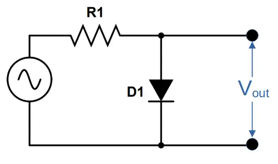
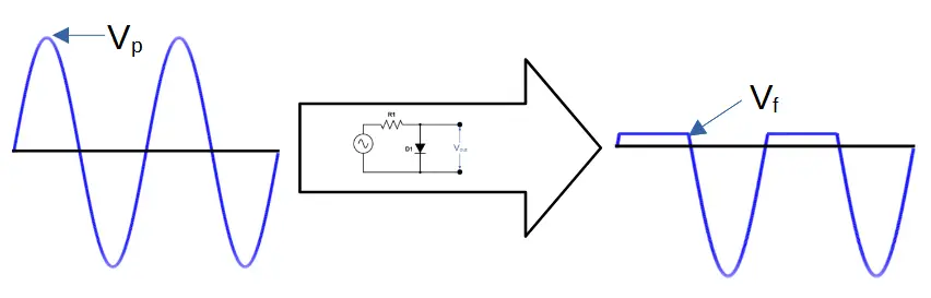
Positive Shunt Diode Clipper
A positive diode clipper limits the output of the positive half-cycle of the input waveform. This type of clipper is also known as a shunt or parallel-positive type of clipper.
In a positive diode clipper, the diode is forward biased (anode more positive than cathode) during the positive half cycle of the sinusoidal input waveform.
The diode conducts during this time, and the output voltage is a clipped version of input signal. During the positive half-cycle, the diode is forward biased and produces an output voltage equal to the forward voltage of the diode Vf (.7 volts for a silicon diode or .3 volts for a germanium diode).
The diode is reverse biased during negative half-cycle, and does not conduct in this case (i). Instead, the current passes directly through the load, allowing the full waveform to pass.
Positive Shunt Clipper Circuit Diagram
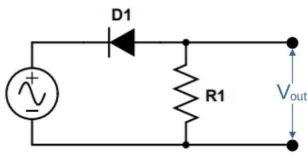
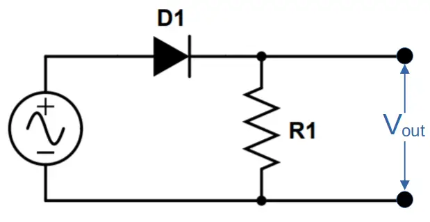
Positive Series Diode Clipper
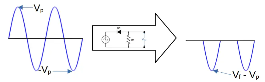
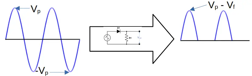
Like the positive shunt clipper, the positive series clipper ‘clips’ the positive half of the waveform.
Unlike the positive shunt clipper, the positive half-cycle is completely clipped since the diode is reverse biased.
The negative half-cycle also passes a slightly weaker (i.e. more positive/less negative) signal as the maximum voltage is reduced by the diode forward voltage Vf.
Thus the output is zero (0) for the positive half-cycle and Vf – Vp for the negative half-cycle.
Positive Series Clipper Circuit Diagram
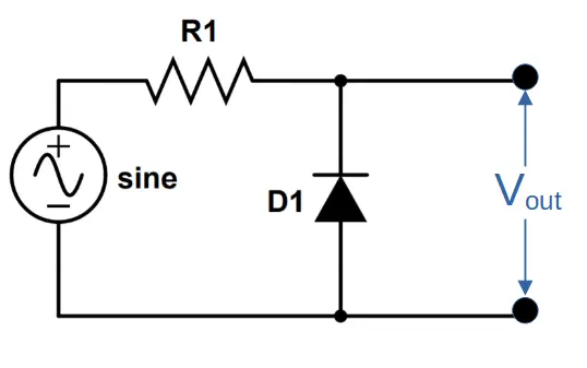
Negative Shunt Diode Clipper
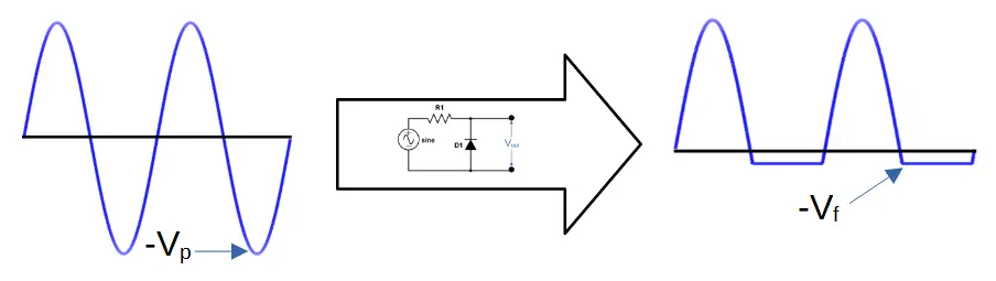
A negative diode clipper circuit clips the negative half-cycle of an input source. It operates in the opposite fashion as a positive diode clipper. This type of clipper is also known as a shunt or parallel-negative type of clipper.
In a negative diode clipper, the diode is forward biased (anode more positive than cathode) during the negative half cycle of the input waveform.
During the negative cycle, the diode conducts, and the current flows through it to ground. The voltage drop across this conducting path is equal in magnitude but opposite polarity (i) from that of a positive clipper circuit.
The output waveform has been clipped at -Vf (-.7 volts) during negative half-cycles because the voltage across the diode is held constant by the forward voltage of the diode.
Negative Shunt Clipper Circuit Diagram
Negative Series Diode Clipper
The negative series clipper performs the opposite action as the positive series clipper.
Like the negative shunt clipper, it ‘clips’ the negative half-cycle of the waveform.
The positive half-cycle features a voltage output that is limited by the forward voltage of the diode, Vf.
Thus the output for the positive half-cycle is Vp – Vf, and the output for the negative half-cycle is zero (0).
Negative Series Clipper Circuit Diagram
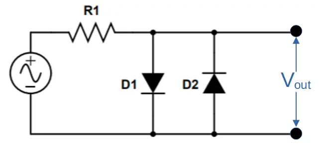
Combination (Dual) Shunt Diode Clipper
A combination diode clipper uses two diodes in parallel, with one functioning as a positive clipper and the other functioning as a negative clipper.
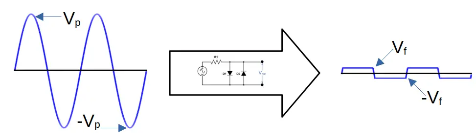
The output voltage of this clipper is a waveform that is clipped during both the positive and negative half-cycles.
If silicon diodes are used, the positive voltage will be limited to +.7 volts, and the negative voltage will be limited to -.7 volts.
Combination Shunt Clipper Circuit Diagram
Biased Diode Clippers
Biasing a diode clipper circuit allows us to design circuits that can clip at specific voltages instead of being limited by the forward voltage of the diode(s).
In order to achieve this, a bias voltage of Vbias is added in series with the diode. This can be accomplished by adding a voltage source like a battery.
The addition of Vbias makes it more difficult to forward bias the diode, with the new voltage required now being equal to Vf (diode forward voltage)+ Vbias.
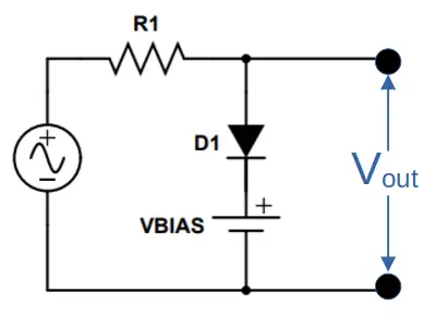
Positive Biased Shunt Diode Clipper
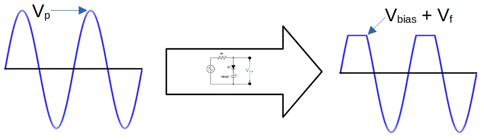
A positive biased diode clipper circuit is designed to clip the positive half-cycle of the waveform at a voltage of +Vbias.
This is because the diode will not become forward biased until the total voltage level reaches Vforward + Vbias. Under this level, the diode remains reverse biased and the signal experiences a short circuit through the load.
The complete negative half-cycle is also allowed to pass because the diode remains reverse biased.
Positive Biased Shunt Clipper Circuit Diagram
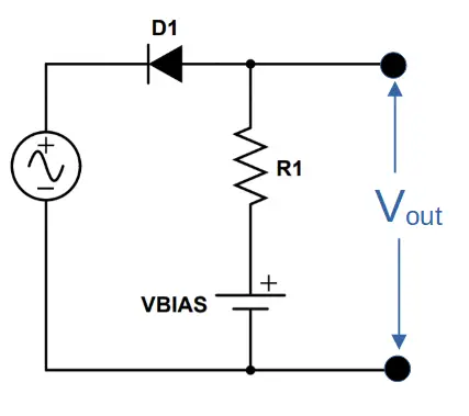
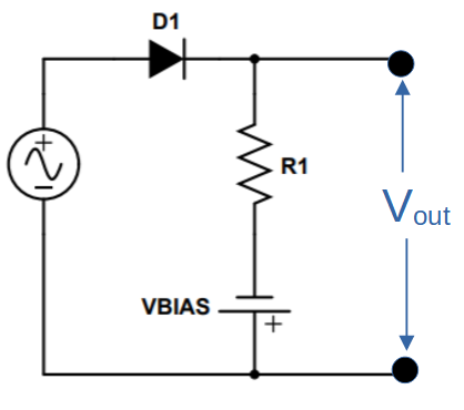
Positive Biased Series Diode Clipper
The positive biased series clipper clips the positive half-cycle of the wavefunction.
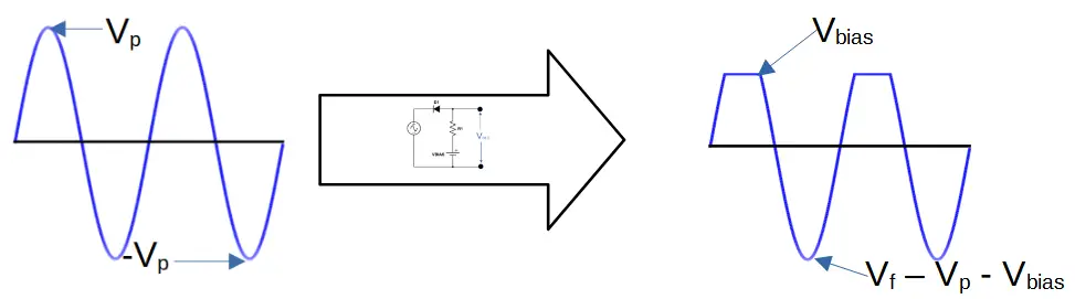
The positive half-cycle has a peak voltage of Vbias, because the output is taken off the biasing voltage source (Vbias) and the resistor R1.
The negative half-cycle is also shaped by the biasing voltage. The output of the clipper sees the negative voltage of the source (-Vp), the voltage from the biasing source (-Vbias), and the forward voltage of the diode, which opposes the other two voltage sources (Vf).
Therefore the positive half-cycle has a maximum voltage of Vbias, and the negative half-cycle has a minimum voltage of Vf – Vp -Vbias.
Positive Biased Series Clipper Circuit Diagram
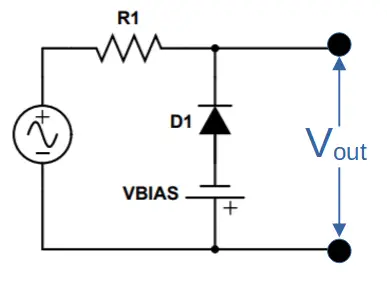
Negative Biased Shunt Diode Clipper
The negative biased diode clipper is the opposite of the positive biased diode clipper.
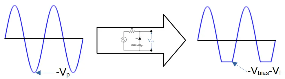
It produces a waveform that has a clipped negative half-cycle, which can be tuned by adjusting the bias voltage level.
The complete positive half-cycle is also allowed to pass because the diode is reverse biased, thus allowing the signal to short through the load.
Negative Biased Shunt Clipper Circuit Diagram
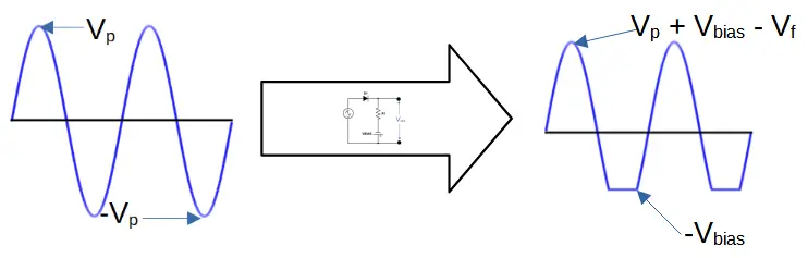
Negative Biased Series Diode Clipper
Negative biased series clippers have the opposite action of positive biased series clippers.
The positive half-cycle sees a maximum voltage of Vp, which adds to the voltage from the biasing source Vbias. However, a voltage drop also occurs due to the diode forward voltage Vf.
During the negative half-cycle, the diode is reverse biased so that current cannot pass. The only voltage measured therefore comes from the biasing source, -Vbias.
Therefore the positive half-cycle passes a maximum voltage of Vp + Vbias – Vf, and the negative half-cycle passes a minimum voltage of -Vbias.
Negative Biased Series Clipper Circuit Diagram
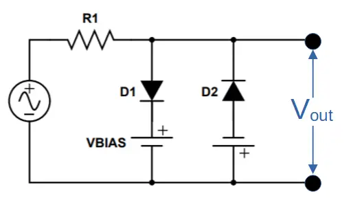
Combination (Dual) Biased Shunt Diode Clipper
The combination biased diode clipper is like placing two biased clippers in parallel.
One diode clips the positive half-cycle of the waveform to the level equal to V1bias + V1forward. A second diode clips the negative half-cycle of the waveform to the level equal to -V2bias-V2forward.
This allows us to produce a waveform that is clipped on both the positive and negative half-cycles.
Combination Biased Shunt Clipper Circuit Diagram
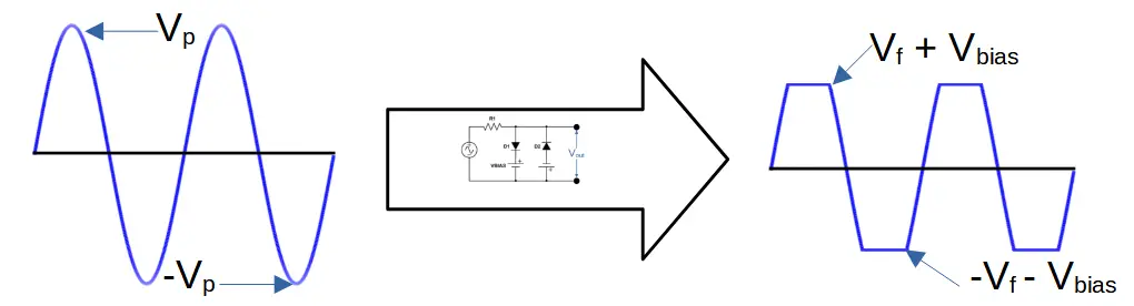
The main advantage of this type of clipper circuit is that it can prevent an output signal from exceeding voltage limits for both half-cycles of the waveform, thus providing total control over the positive and negative limits of the output.
The disadvantage of this type is that it requires twice the number diodes as a single biased clipper, as well as two voltage sources. Thus it also consumes more power.
Zener Diode Clipper Circuits
One of the primary challenges with using biased clippers is that they require additional voltage sources, adding cost and complexity to the overall design.
One solution to this is by using Zener diodes, which clip both sides of the waveform.
An additional advantage is that there are many Zener diodes available, with a large range of Zener voltages. This allows us to design circuits that can clip one or both half-cycles of a waveform to a custom level designated by the Zener voltage.
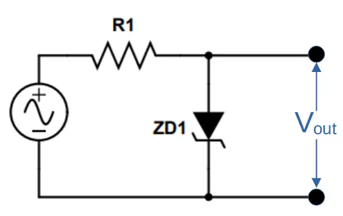
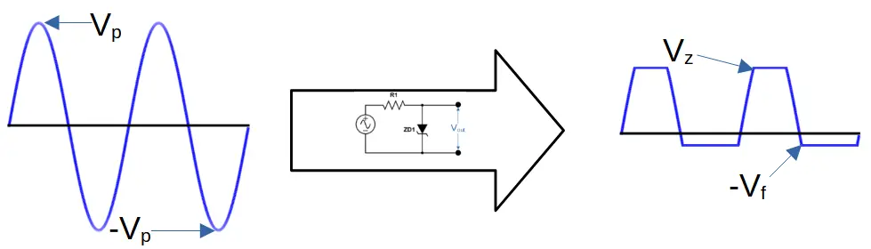
Positive Zener Diode Clipper
A positive Zener diode clipper uses a Zener diode in the same configuration as a regular diode in a positive diode clipper circuit.
Both a regular diode and a Zener diode will clip the positive half-cycle of the input waveform to the level of the forward voltage (VF).
However, the Zener diode also allows current to flow through it when the voltage reaches the Zener voltage VZ.
This means that the negative half cycle is clipped to the Zener voltage (technically -VZ)
Thus a single Zener diode can be used to clip both sides of the waveform.
Positive Zener Clipper Circuit Diagram
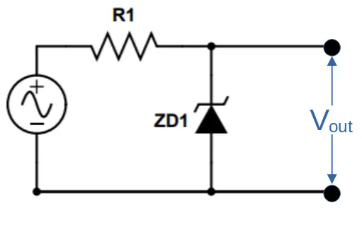
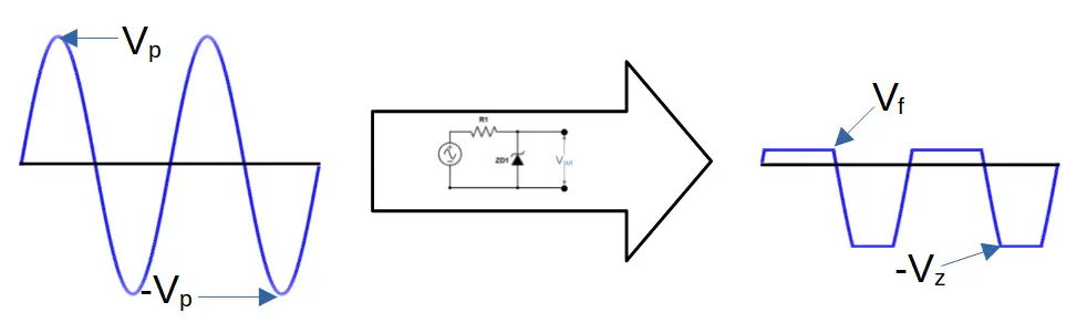
Negative Zener Diode Clipper
A negative Zener diode clipper has the diode in the opposite configuration to the positive Zener diode clipper.
In this case, the negative half-cycle is clipped to the forward voltage VF, and the positive half-cycle is clipped to the Zener voltage, VZ.
Negative Zener Clipper Circuit Diagram
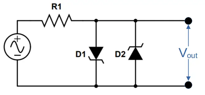
Combination (Full-Wave) Zener Diode Clipper
Zener diodes can also be used to clip both halves of the waveform. A full-wave Zener diode clipper has a positive and negative half cycle both clipped to VZ.
The Zener diodes do not have to be identical. By using two Zener diodes, each with a different Zener voltage, it is possible to clip each half-cycle of the waveform to specific voltages.
Combination Zener Diode Clipper Circuit Diagram
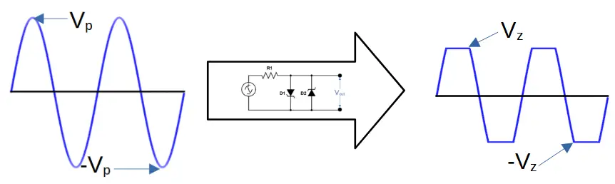
Combined with the availability of Zener diodes with a wide range of Zener voltages, this makes the combination Zener diode clipper an incredibly useful circuit.
Conclusion
In conclusion, we have seen that a variety of clipper circuits exist. They are used to clip a waveform’s voltage, so that it is within the desired range of voltages for use in circuits.