Resistors in Series
Resistors can be found in virtually every circuit on the planet. This is for good reason; resistors give us the ability to control the flow of current by restricting the flow electricity, and to establish reference voltages for sub-circuits.
Resistors are one of the most important electric components. Resistors are components that are used to add resistance to electrical circuits. When resistors are place in series, the total resistance equals the sum of the individual contributions from each resistor.
They are often used in series and parallel arrangements for a variety of reasons. Understanding how resistors function in series is an important step toward more complex configurations of resistors and other components. This lesson will also strengthen your ability to read electrical schematics and reinforce the concepts that were introduced in Module 1 and Module 2. That will help give you the ability to analyze more complex circuits, leading up to Kirchoff’s Current and Voltage Laws.
Review of Resistors
Resistors are electrical components that allow electric current to flow, but not as easily as a regular wire or conductor. Instead, they reduce the current flowing through them by an amount proportional to the resistance in ohms:
I = \frac{V}{R}Let’s say we have a 12 volt battery connected to a 1 ohm resistor. Ohm’s Law states that the current (I) is equal to the battery voltage (V) over the value of the resistor (R):
I = \frac{V_{battery}}{R} = \frac{12V}{1\Omega}=12\ AmpsFor a review on this topic check out our lesson on Ohm’s Law!
If we were to use a bigger resistor of, let’s say, 15 Ohms, then we would reduce the current much more:
I = \frac{V_{battery}}{R} = \frac{12V}{15\Omega}=.8\ AmpsResistors reduce current, and bigger resistors reduce current more.
They also produce a voltage drop that is also proportional to the resistance:
V = I R
In the last two cases, we know that the voltage drop must be equal to the battery voltage. That’s because on either side of the battery’s terminals, we will always measure the potential difference supplied by the battery. Batteries wouldn’t be very good voltage sources if this wasn’t the case.
However if two resistors are placed in series, the total voltage drop would be equal to the battery voltage.
Resistors are Useful
Resistors function by dissipating power:
P = I^2R
Resistors convert electrical energy into thermal energy (heat) as current passes through them. This is the most basic function of the resistor. This power dissipation is also known colloquially as an “I-squared R loss”.
Because resistors conduct inefficiently, they convert some of our electricity into heat.
Why would we want this?
There are actually a couple of reasons:
- Resistance doesn’t just waste energy; it also reduces current flow. Some resistance is always needed to prevent a short circuit. Even though conductors have a small amount of resistance, a higher level of resistance is usually needed to limit the current to safe levels. This is why it’s important to always use one resistor in series or in each branch of a parallel circuit.
- When we use specific values and configurations of resistors, we can tweak our circuit to take a given power source and output a specific current, or voltage levels, as needed.
It’s a lot easier to use resistors to dial in the current we need than it is to add a new, highly specific battery every time we need a new current.
Return to…the Resistance!
Let’s return to the concept of electrical resistance for just a moment. Resistance is basically how conductive something is.
It’s important to remember that everything in a circuit (other than a superconductor) has some resistance. Every element (resistors, inductors, diodes, transistors) has resistance. The wires themselves have resistance. Even wires made of silver, which has the highest conductivity of any metal, has some resistance. It’s a low amount of resistance, but it’s still there.
So resistance is a constant factor in any circuit.
Resistors in Series
To get the total resistance in a series circuit (or a single branch of a parallel circuit), you just add up the resistances of everything in the circuit (or branch).
R_T = R_1 +R_2+R_3+...+R_N
It’s really convenient that resistance adds so easily. Plus, the resistance added by things like wires and switches is low enough that we usually ignore it.
The concept of resistance adding in series is easy to understand intuitively. Since every conductor has resistance, the longer the conductive path is, the higher the resistance would be. Resistors just make it easier to obtain a reliable resistance, so you don’t need to add 50 feet of extra wire when you want to increase the resistance.
Unwanted Resistance Can be a Bad Thing
Unless we’re using resistance for a specific function in a circuit, resistance is usually a bad thing. The fact that resistance adds when conductors (or resistors) are placed in series, can make these problems significant.
For example, resistance can be an important factor to consider when installing new wiring. Wire runs longer than a few feet often require resistance of the wire to be taken into account. Fortunately, resistance decreases as the size of the wire increases. This means that wires of a specific length may have a recommended ‘gauge‘ to prevent resistive losses from taking a toll on the system. Check out our article on wiring for more information.
Another great example is power transmission. When we’re transmitting electricity long-distance, the resistance of the wires becomes a really big deal. It was actually the deciding point between Edison’s DC (direct current) power and Westinghouse’s AC (alternating current) power. Which is the reason that when you plug a power cord into a wall socket, you’re calling on AC power (not DC!) to supply the electricity you need. We cover AC power and electronics in Module 4. Learning about AC isn’t super important for getting started in electronics, however. It helps. (Just an FYI.)
Alright, let’s get started putting some resistors in series and see what happens!
Putting Resistors in Series
Understanding how resistors function in series is simple: the resistance value R (in Ohms) simply adds.
Consider the following circuit:
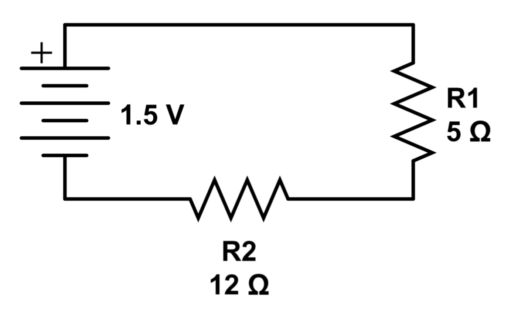
This circuit has a 1.5V battery sources and two resistors; R1 with a resistance of 5Ω, and R2 with a resistance of 12Ω. Resistance values in series add, so the total is:
R_T = R_1 + R_2 = 5\Omega + 12\Omega = 17\Omega
You’ll not that we are using the designation RT to describe the total resistance of the circuit. Sometimes you might also see Req used, in order to designate the equivalent resistance of a circuit or parallel branch of a circuit.
Equivalent resistance just means that we are pretending some number of resistors are a single resistor. They can be arranged in series, in parallel, or in some crazy combination. We can always analyze the circuit and figure out how much resistance the circuit has, in total. The total amount of resistance is called the equivalent resistance, designated at Req.
Keep in mind that (disregarding superconductors), every wire or component has some resistance. So the real-life exact equivalent resistance would need to include the resistance of each component and wire. In electronics, sometimes we do ‘hand-wavy’ approximations that function very well. Ignoring the resistance of everything other than resistors works just fine.
Analyzing Resistors in Series
We’ve talked about what happens to resistance when resistors are placed in series, but what about current, voltage, and power?
Current for Resistors in Series
Let’s start with current. Adding a resistor, or multiple resistors in series, has the same effect on current as using a bigger resistor. The higher the total resistance, the lower the current. It’s exactly the same as the Ohm’s Law example we saw above.
Here’s the (slightly) tricky part: Current does not ‘drop’ across each resistor like voltage does. The current through the entire circuit, through every resistor, is exactly the same. Adding a resistor decreases the current through all of the resistors.
One nice side effect is that we only have to keep track of one current. It’s the same everywhere. Let’s look at an example or two.
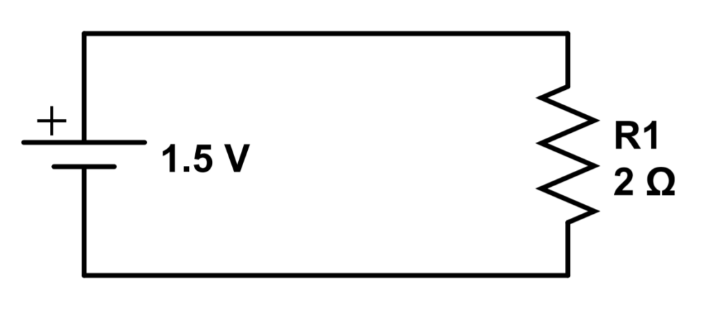
For comparison, let’s look at this simple circuit with a 2 Ohm resistor connected to a 1.5 Volt battery. The current will simply follow Ohm’s Law, using the battery voltage and the resistance of the single resistor (R1).
I = \frac{V_{battery}}{R_1} = \frac{1.5V}{2\Omega}=.75\ AThe current in the circuit is .75 amps.
Now let’s add a second resistor to the circuit.
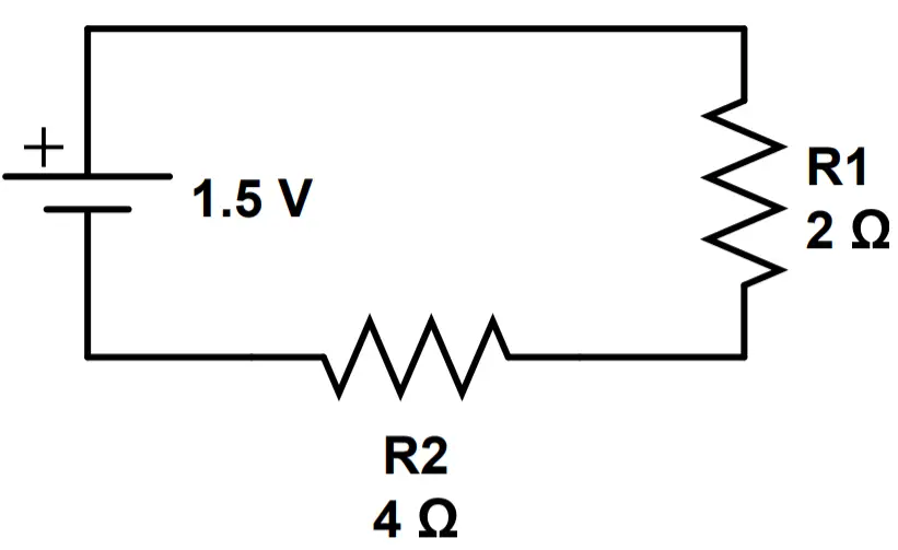
This time, the current will depend on the resistance of both R1 and R2. We’ll designate the total resistance as RT:
I = \frac{V_{battery}}{R_T} = \frac{V_{battery}}{R_1+R_2} = \frac{1.5V}{2\Omega + 4\Omega}= \frac{1.5V}{6\Omega}=.25ABy adding the second resistor, we decreased the current from .75 amps to .25 amps. The new current is the same through the entire circuit. We have .25 amps going through resistor R1 and .25 amps going through resistor R2.
We can now see that adding a resistor has the function of decreasing the current through the entire series circuit. In the next lesson (resistors in parallel), we’ll find that each branch has a different resistance.
Voltage for Resistors in Series
There are two things to keep in mind regarding voltage when looking at resistors in series:
- The total voltage across the whole circuit is the same (the battery or voltage supply voltage).
- The voltage ‘drop’, ie, potential difference across each individual resistor, is now different. In other words, we now have a V1 that corresponds to R1, a V2 that corresponds to R2, etc. The total voltage VT across all of the resistors is the same as the battery or voltage supply voltage (see point #1).
Let’s look again at the two circuits we just analyzed for current, to see how adding a resistor changes the voltage at different points in the circuit.
With one resistor, the voltage across the resistor is the same as the battery voltage, 1.5 volts. This is what we expect because if you measure the voltage across the battery without a circuit, we would measure 1.5 volts.
Let’s add R2:
With a second resistor, the 1.5 volt battery voltage is now dropped across both resistors. Each one contributes to the total voltage. Now we have V1 which is the voltage across R1 and V2, the voltage across R2. The sum of V1 and V2 will equal VT, which is the battery voltage. Let’s calculate V1 and V2 using the current of .25A that we calculated above. Remember, the current I through both resistors is the same!
V_1 = IR_1=(.25A)(2\Omega)=.5V \\
V_2 = IR_2 = (.25A)(4\Omega)=1V
Let’s check to see if we did this right. If we calculated correctly, the total voltage should add up to the battery voltage (1.5V).
V_T = V_1 + V_2 = .5V + 1V = 1.5V
As we can see, VT, which is the sum of the voltage drops across both resistors, is the same as the battery voltage. This provides a nice double check.
Power for Resistors in Series
It turns out that with more resistance, there is less power dissipation in the circuit. One way to think about it is like this: an open circuit (i.e. disconnected) would not result in any power dissipated or supplied. On the other hand, a short circuit (connected to voltage source with no resistance) would result in a huge amount of power supplied and dissipation. If you accidentally connect the two terminals of a battery without any resistance, the battery will discharge very quickly.
Let’s return one more time to our two example circuits to see how power is affected by adding a resistor.
Power dissipation is given by the formula P=I2R. We found earlier that the current is equal to .75A.
P = I^2R = (.75A)^2(2\Omega) = (.5625)(2) = 1.125W
The power dissipated by the resistor is 1.125 watts. What is the power supplied (Ps) by the battery?
P_s = IV = (.75A)(1.5V)=1.125W
The power supplied by the battery is identical to the power dissipated by the resistor. This calculation functions as double check that we calculated the power dissipation correctly.
Let’s add our second resistor and see what happens to power!
This time, R2 is reducing the amount of current drawn by the circuit. Our two resistors, R1 and R2, are both dissipating power, which we’ll call P1 and P2. respectively. We can calculate the power dissipated by each resistor by using the individual voltage drop across each resistor. Recall that the current in the circuit is reduced to .25A by adding the second resistor.
P_1=I^2R_1=(.25A)^2(2\Omega)=.125W \\
P_2=I^2R_2=(.25A)^2(4\Omega)=.25W \\
P_T=P_1+P_2=.125W+.25W=.375W
We can see that adding a second resistor reduced the power from 1.125W to .375W.
Let’s confirm that we calculated correctly by double-checking our result against the power supplied by the battery.
P_s = IV = (.25A)(1.5V)= .375W
Nice job!
Now that we have seen what happens to resistance, current, voltage, and power with resistors in series, let’s tackle some examples.
Example Problems
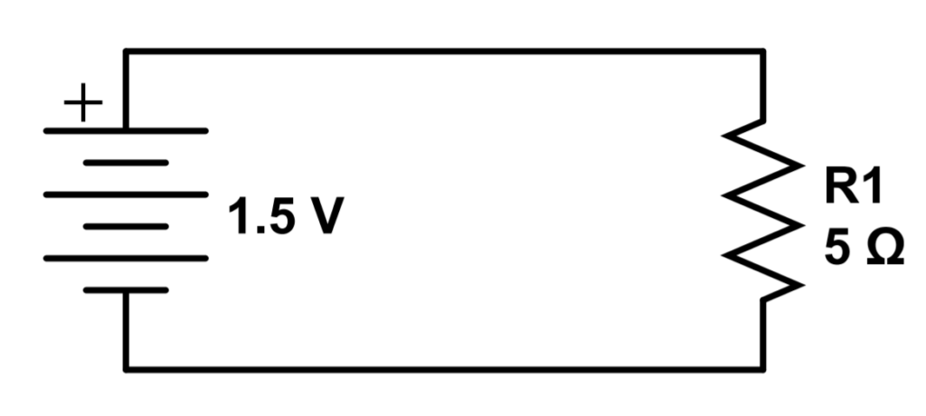
Example 1 – A single resistor
Let’s return to the example of a single resistor so that we can continue to practice and develop our intuition. In the following circuit, we can see that we have a single 5Ω resistor connected to a 1.5V battery:
Try to answer the following questions. The answers are just below in case you have difficulty or want to confirm.
1) What is the total resistance of the circuit?
2) What is the current in the circuit?
3) What is the voltage drop across the resistor?
4) What is the power supplied by the circuit?
5) What is the power dissipation (loss) of the resistor?
Answers to Example 1
1) What is the total resistance of the circuit?
R_T = R_1 = 5\Omega
2) What is the current in the circuit?
I = \frac{V}{R} = \frac{1.5V}{5\Omega} = .3A3) What is the voltage drop across the resistor?
V = IR = (.3A)(5\Omega) = 1.5V
4) What is the power supplied by the circuit?
P_s = IV = (.3A)(1.5V) = .45W
5) What is the power dissipation (loss) of the resistor?
P_l = I^2R = (.3A)^2(5\Omega) = .45W
As a double check, the total power supplied should equal the power dissipated. This is the energy supplied to the circuit per unit time.
Let’s compare this with two resistors in series to see how our results change.
Example 2 – Two Resistors in Series
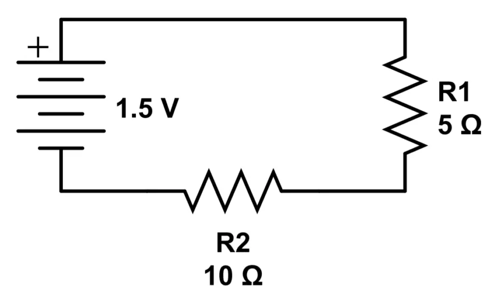
In this case, we have two resistors in series: R1, with a value of 5Ω, and R2, with a value of 10Ω.
Try to answer the following questions:
1) What is the total resistance of the circuit?
2) What is the current in the circuit?
3) What is the voltage drop across each resistor?
4) What is the power supplied by the circuit?
5) What is the power dissipated by each resistor?
Answers to Example 2
1) What is the total resistance of the circuit?
R_T = R_1 + R_2 = 5\Omega + 10\Omega = 15\Omega
We can see that the resistance has increased by the value of the second resistor.
2) What is the current in the circuit?
I = \frac{1.5V}{15\Omega} = .1AThe current has decreased because the resistance in the circuit is higher.
3) What is the voltage drop across each resistor?
Remember: The current through each resistor is the same in a series circuit.
V_1 = IR_1 = (.1A)(5\Omega)=.5A
V_2 = IR_2 = (.1A)(10\Omega)=1A
The voltage drop across R2 is twice that of R1, because R2 has twice the resistance.
4) What is the power supplied by the circuit?
P_S = IV_T = (.1A)(1.5V) = .15W
The power has decreased because the resistance of the circuit has increased.
5) What is the power dissipated by each resistor?
P_1 = I^2R_1 = (.1A)^2(5\Omega)=.05W
P_2=I^2R_2=(.1A)^2(10\Omega)=.10W
As a double check, Psupply should equal P1 + P2:
P_S = .15W = P_1+P_2=.15W
Let’s build on the skills you have learned, with Lesson 5: Resistors in Parallel.