Capacitors in AC Circuits
Key Points:
- Capacitors store energy in the form of an electric field; this mechanism results in an opposition to AC current known as capacitive reactance.
- Capacitive reactance (XC) is measured in Ohms, just like resistance.
- Capacitive reactance is a significant contributor to impedance in AC circuits because it causes the current to lead the voltage by 90°.
X_C = \frac{1}{\omega C} = \frac{1}{2\pi fC}Why it Matters:
Capacitors are frequently used in AC circuits, most commonly as filters. Capacitors contribute capacitive reactance when used in an AC circuit. The frequency-dependent nature of capacitive reactance allows circuit designers to carefully choose a capacitor. In this lesson, we’ll derive the formula for capacitive reactance and dive into how capacitors work in AC circuits.
Capacitive vs. Inductive Reactance
The chart below presents a summary of key characteristics for capacitors and inductors in AC circuits. This lesson will discuss each of these characteristics for capacitors in detail.
| Store Energy in a | Resulting in | Reactance Value | The current… | Current Equals | |
| Capacitors | Electric Field | Capacitive Reactance (XC) | XC = 1/(ωC) | Leads voltage by π/2 (90°) | IC = ωC Vmax sin(ωt + π/2) |
| Inductors | Magnetic Field | Inductive Reactance (XL) | XL = ωL | Lags voltage by π/2 (90°) | IL = (1/ωL) Vmax sin(ωt – π/2) |
Review of Impedance
We saw in the last lesson that impedance is the total opposition to the current flow in AC circuits. Impedance is the AC circuit analog of resistance in a DC circuit.
We learned that resistance is just one part of impedance; impedance also takes into account something called reactance. Impedance is the sum of resistance and reactance:
Impedance = Resistance + Reactance
We found that both capacitors and inductors contribute reactance. Reactance, in essence, is the opposition to current caused by a phase shift in which the voltage across a capacitor or inductor is no longer in phase with the current.
The reactance contributed by capacitors is called capacitive reactance, and the reactance contributed by inductors is called inductive reactance. So impedance is the sum of resistance and both types of reactance:
Impedance = Resistance + Capacitive Reactance + Inductive Reactance
Resistance is different from reactance, however, because it results in energy loss from the circuit. Reactance results in stored energy. In order to differentiate and track this important difference, reactance is multiplied by a complex number, ‘j’, which is the square root of -1.
Before we dive further into the math behind reactance, let’s review how capacitors function in an AC circuit.
Capacitors in AC Circuits- Conceptual Analysis
As a reminder, capacitors consist of conductors separated by a dielectric, or insulating, material. Capacitors store energy in an electric field; as current is applied to a capacitor, the molecules in the dielectric become polarized. This is the electrical equivalent to storing energy in a spring; when the current is changed, the molecules in the dielectric ‘spring back’ to their normal (resting) positions, driving current in the direction opposite to the originally applied current.
In an AC circuit, a capacitor will start to store energy as a positive voltage is applied. The applied voltage reaches a peak and then reduces to zero (and then goes negative) following the sine wave. Just as the voltage from the source reaches zero, the voltage across the capacitor is at its’ highest. Then, when the voltage from the supply begins to reverse direction, the capacitor will start to release the energy that was just stored in its dielectric. The capacitor discharges, but the current it produces is not in phase with the source voltage. This is because the peak of the current produced by the capacitor occurs as the voltage across it reaches zero. In addition, the current produced by the capacitor is in the opposite direction of the current that caused the capacitor to charge. The current leads the voltage by 90 degrees.
Since the current created by the capacitor’s discharge is no longer in phase with the voltage, it actually works against it. Think about two waves crashing into each other; they cancel out some of each other’s movement. This opposition to current results in capacitive reactance.
Capacitors in AC Circuits- Mathematical Analysis
Having a conceptual understanding of how capacitors in AC circuits function is important (and strangely satisfying), but there should be a mathematical explanation for what’s happening. We can build our mathematical model by using KVL to analyze a capacitor in an AC circuit.
Let’s look at an AC circuit consisting of a capacitor and AC source:
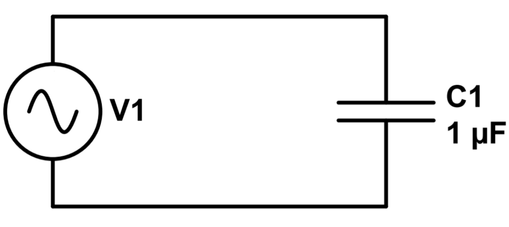
We can apply Kirchoff’s Voltage Law (KVL) to analyze this circuit. This entails adding the voltage contributions of each circuit element and setting them equal to zero. We follow the convention of calling a voltage ‘drop’ positive and a voltage source negative (the opposite approach will work as well). Our goal is to find the current in the circuit.
The contribution of the voltage source is a sinusoidal voltage of frequency f. We simplify the equation a bit by using a common abbreviation, ω = 2πf. So the source voltage will look like this:
V_{source} = V_{max} sin(2\pi ft)=V_{max}sin(\omega t)To do our KVL analysis, we also need the voltage across the capacitor. The voltage across the capacitor is the charge ‘q’ divided by the capacitance ‘C’ (this relation is covered in our lesson on capacitors):
V_{cap} = \frac{q}{C}Using KVL, the total voltage in the loop is the sum of the voltages, which must be equal to zero. We use the convention of calling voltage ‘sources’ negative and voltage ‘drops’ positive, and set the two terms equal to zero:
-V_{source} + V_{cap} = -V_{max}sin(\omega t) + \frac{q}{C} = 0We can solve for q by moving the sine term to the other side and multiplying by C:
q = CV_{max}sin(\omega t)Note that this is really just the same as the formula for the charge on a capacitor (q = CV), with the addition of a sine term due to the alternating (AC) voltage.
At the end of our lesson on electric current, we saw that current is most correctly described as the derivative of the charge with respect to time, dq/dt. Let’s take the derivative of q with respect to time in order to find the current. Note that the derivative of sine is cosine, and we gain an ω term:
I_C = \frac{dq}{dt} = \frac{d}{dt}(CV_{max}sin(\omega t)) = \omega CV_{max}cos(\omega t)This is a final result, but it would be nice to see how the current, now described by a cosine, relates back to voltage. We can just change the cosine into a sine so that we can see how the current has been affected by the capacitor.
To do this, let’s use the following trigonometric identity:
cos(\omega t) = sin(\omega t +\frac{\pi}{2})Cosine is just equal to sine shifted up by pi/2.
So, the current I is:
I = \omega CV_{max}sin(\omega t + \frac{\pi}{2})Compare this again to the voltage:
V = V_{max}sin(\omega t)We can see that the current is now shifted by an additional term of pi/2. This is the mathematical description of the current leading the voltage by 90 degrees, which we described above.
We can also use our finding to derive the capacitive impedance that we saw in the last lesson.
Derivation of Capacitive Impedance
The current reaches its maximum value when the sine term is equal to one (1):
I_{max} = \omega CV_{max}We now define capacitive reactance (XC):
X_C = \frac{1}{\omega C}So that the current is now the voltage over the capacitive reactance (XC):
I_{max} = \frac{V_{max}}{X_C}Why would we do this? For one, this formula now resembles Ohm’s Law. Capacitive reactance also now has units of ohms, so it’s compatible with resistance to compute impedance. It’s just a handy ‘tool’ to make things a little easier.
Now that we understand capacitors in AC circuits, let’s continue to learn, with Lesson 5: Inductors in AC Circuits.