Capacitor Filters
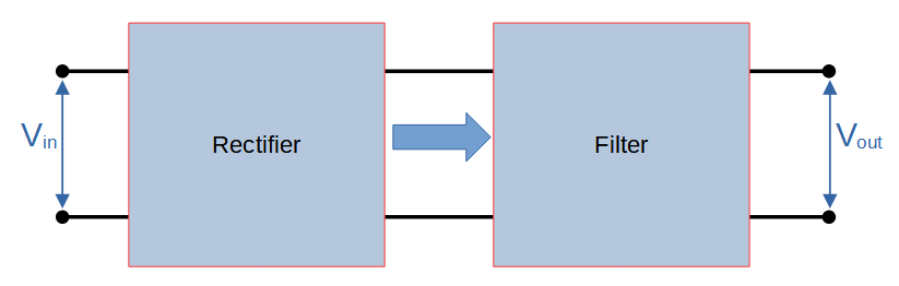
The most common way to convert an AC signal into DC is by using a rectifier. The main limitation of rectifiers, however, is that they produce a pulsed DC output instead of an ideal, flat DC profile. Filters are commonly used after rectification in order to improve the quality of the output signal. Capacitor filters are one of the most common types.
Capacitor filters use a capacitor to improve the waveform quality coming from a rectifier circuit. The capacitor itself is frequently referred to as a smoothing capacitor.
Rectifiers produce a pulsed DC output, and a smoothing capacitor can be used to store charge while the pulse is at its’ peak and generate a voltage when it falls. This greatly improves the quality of the output waveform.
Like other rectifier filters, the filter is applied directly after the rectification stage.
One advantage of capacitor filters that makes them very common is that capacitors generally cost much less than inductors. Capacitors can be purchased at extremely low cost, making them a great solution for many applications. Even when a single smoothing capacitor is not sufficient, they are still favored as a critical component of most rectifier filters. They are commonly used in conjunction with an inductor (LC filter), and even more commonly as a ‘pi’ configuration with two capacitors and an inductor producing a dramatically improved output (CLC filter).
In this lesson, we will learn how capacitor filters work and why they are so useful.
Smoothing Capacitor
In order to understand capacitor filters, it’s helpful to think of a rectifier as producing a combination of both DC and AC components.
An ideal AC to DC converter would output a signal with no (zero) AC component and 100% DC component.
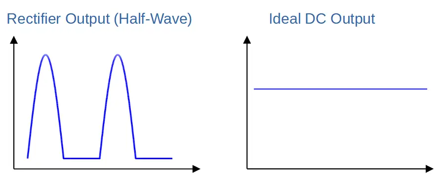
Instead, rectifiers produce a pulsed DC output that has relatively poor characteristics. This seems obvious because a pulsed signal does not bear much resemblance to a flat DC signal, but it is also reflected in properties like a high ripple factor. This indicates that the AC component within the output signal is large.
Rectifier filters that use a combination of capacitors and/or inductors are used to improve the output of a rectifier by reducing the AC component and increasing the DC component in the output.
The effect of the capacitor can be thought of as smoothing out the waveform.
Capacitor Filter Circuit
A capacitor filter is constructed by placing a single capacitor in parallel with the load.
Capacitor Filter Circuit Diagram
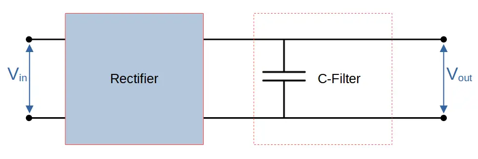
This allows the capacitor to function as a charge storage device and voltage source.
The primary function of the capacitor is to charge when the supplied voltage exceeds the voltage across the capacitor, and to discharge when it drops below the capacitor voltage.
Thus the capacitor smooths out the voltage by acting as a voltage source.
How Capacitor Filters Work
Capacitor filters have two cycles of operation: a charging cycle, and a discharging cycle. Together, the two cycles span one full cycle of the rectifier output.
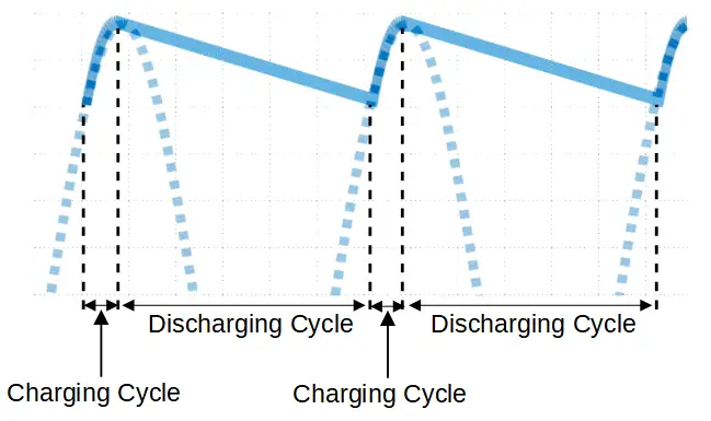
Smoothing Capacitor Charging Cycle
The capacitor charges during the first cycle.
This occurs when the voltage from the rectifier is higher than the voltage across the capacitor.
During the very first cycle (i.e. startup), the charging cycle will begin at t=0 and end when the voltage is at its’ peak.
For all subsequent cycles, the charging cycle begins when the voltage from the rectifier is greater than the voltage across the capacitor.
The charging cycle always ends when the voltage from the rectifier begins to decrease, i.e. at the peak of the voltage waveform.
Smoothing Capacitor Discharging Cycle
The smoothing capacitor begins to discharge when the voltage from the rectifier starts to decrease. The capacitor tries to maintain the peak voltage and generates a voltage across the load. This occurs because capacitors generally discharge more slowly than the waveform changes.
As the capacitor discharges, the voltage decreases. However the output is dramatically improved compared with the output of the rectifier alone.
Mathematically, the voltage produced by the capacitor can be described by the following exponential relation:
V_C(t)=V_me^{-\frac{t}{R_LC}}Because the capacitor is functioning as a second voltage source, the circuit can be treated as containing two voltage sources in parallel: (1) the rectifier and (2) the capacitor. Voltage sources in parallel do not result in an increase to the total voltage; instead, the source with the greater voltage dictates the voltage drop. Having two sources in parallel can potentially increase the total current supplied, but not the voltage.
As long as the value of the capacitor and/or load resistor is high enough (i.e. RLC >> T), the voltage from the capacitor VC will exceed the voltage produced by the rectifier. Because the two voltage sources (rectifier and capacitor) operate in parallel, they do not add; the greater voltage supplied by the capacitor functions as the total output VO. In other words,
V_O=V_C(t)=V_me^{-\frac{t}{R_LC}}The discharge cycle ends when the voltage from the rectifier once again exceeds the voltage across the capacitor.
As the voltage increases, the capacitor begins to charge again, completing the cycle.
Capacitor Filters in Power Supplies
Capacitors serve a critical filtering function in power supplies, because an ideal power supply produces a flat DC waveform rather than the pulsating DC output of a rectifier.
Most power supplies therefore utilize a rectifying circuit followed by a filter circuit that includes at least one smoothing capacitor.
Capacitor Filter in Half-Wave Rectifier
The capacitor stores charge when the voltage is increasing during the ‘upward’ section of the wave. A corresponding voltage is generated across the capacitor.
When the voltage begins to decrease, the capacitor begins to act as a second voltage source, releasing the charge it has stored.
Instead of dropping to zero, the new waveform slowly declines from the peak voltage as the capacitor discharges.
Thus the capacitor buffers the total voltage measured across the load.
The capacitor then recharges during the next cycle, and the process begins again.
This results in a waveform that much more closely resembles an ideal DC signal, which would be a flat line.
Capacitor Filter in Full-Wave Rectifier
The full-wave rectifier produces a higher quality output signal than the half-wave rectifier. However it still features pulses that decline all the way to zero and then rise back up the peak.
Like half-wave rectifiers, the output of the full-wave rectifier can be significantly improved by adding a capacitor to the circuit.
Full-Wave Rectifier Capacitor Filter Circuit Diagram
The capacitor stores charge when the voltage is increasing during the ‘upward’ section of the wave. A corresponding voltage is generated across the capacitor.
When the voltage begins to decrease, the capacitor begins to act as a second voltage source, releasing the charge it has stored.
Instead of dropping to zero, the new waveform slowly declines from the peak voltage as the capacitor discharges.
Thus the capacitor buffers the total voltage measured across the load.
The capacitor then recharges during the next cycle, and the process begins again.
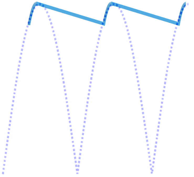
This results in a waveform that much more closely resembles an ideal DC signal, which would be a flat line.
Other Types of Capacitor Filters
Capacitors are used as integral components of many different types of filter circuits. The filters introduced below perform a different function than rectifier filters.
Rectifier filters are used to improve the quality of a waveform coming from a rectifying circuit. Their job is to produce the best DC signal possible.
In contrast, the following electronic filters are designed to remove unwanted frequencies from a signal that contains a variety of AC frequencies. They produce an AC signal.
Low-Pass Filter
Capacitors are critical to low-pass filters, where they provide capacitive reactance that is used to filter out high frequencies. Since capacitive reactance is inversely proportional to frequency, the output of a low pass filter is taken across the capacitor, which primarily drops low frequencies.
High-Pass Filter
Capacitors are also used in high-pass filters. High pass filters use capacitors in the reverse orientation as low-pass filters. A capacitor is used in series in order to attenuate low frequencies, allowing high frequencies to pass to the filter’s output.
Band-Pass Filter
Band-pass filters use a combination of low and high pass filters to allow a specific frequency band (called a passband) to pass and attenuating the frequencies around it.
Band-Stop Filter
Band-stop filters, like band-pass filters, use a combination of low and high pass filters. However in this case the filters are used to filter out a specific band of frequencies called a stop band.