Op Amp Comparator
An op amp comparator is a circuit that uses an operational amplifier to compare two voltages. It functions by comparing two voltages and outputting a high or low signal.
One of the most important uses of the comparator is in analog to digital conversion. The inputs to the comparator can be any value, but the output is confined to either the high or low state. This means that part of its’ basic functionality is to convert an analog signal into a digital one.
Like other op amp circuits, the op amp comparator relies on the fundamental functionality of an operational amplifier in order to function. It can be considered the simplest type of op amp circuit because it uses the op amp without any feedback.
In this article, we will cover how op amp comparators work, the two primary op amp comparator configurations, and some common examples of real-life op amp comparator circuits.
- How Op Amp Comparators Work
- Op Amp Review
- How an Op Amp Works in a Comparator
- Op Amp Comparators vs. Other Op Amp Circuits
- Op Amp Comparator Circuits
- Non-Inverting and Inverting Op Amp Comparators
- Non-Inverting Op Amp Comparator
- Inverting Op Amp Comparator
- Op Amp Comparator With Hysteresis
- Op Amp Comparator Truth Table
- Op Amp Comparator Applications
- Op Amp Comparator IC
How Op Amp Comparators Work
An op amp comparator is a type of circuit that relies on the basic functionality of an operational amplifier. It takes two inputs and determines which voltage is greater, even if the difference is minute.
Let’s review the basic operation of an op amp so that we can understand how the op amp comparator functions.
Op Amp Review
An operational amplifier is a type of analog circuit. It is normally used in the form of an integrated circuit, although they can be constructed out of transistors and other basic components. In practice, circuit designers use standard op amp integrated circuits (ICs) due to ease of use and predictability.
When op amps are used in a circuit’s design, its’ inner workings are generally abstracted away. This means that we don’t worry about the operation of the components within the amp; we can simply learn about the op amps themselves.
How an Op Amp Works in a Comparator
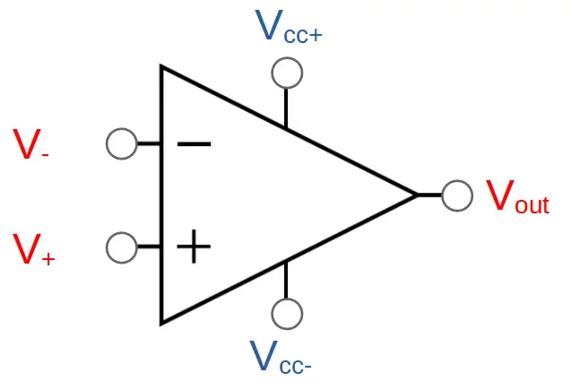
Operational amplifiers have two inputs, called the inverting input (V–) and the non-inverting input (V+).
Op amps have a single output, Vout.
They also have two power supply connections; a high voltage (Vcc+) and a low voltage (Vcc-). These connections are not considered ‘inputs’ but they do power the op amp and determine the maximum high and low voltages it can output.
When the voltage on the non-inverting input (V+) is greater than the inverting input (V–), the op amp will drive the output higher. It will increase the output until either: (1) The two inputs are equal, or (2) The output equals Vcc+.
When the non-inverting input (V+) is less than the inverting input (V–), the op amp will drive the output lower. It will decrease the output until either: (1) The two inputs are equal, or (2) The output equals Vcc-.
Op Amp Comparators vs. Other Op Amp Circuits
Most op amp circuits use feedback to the inverting input. This allows the op amp to keep the input voltages the same.
The op amp comparator is different. It doesn’t use any feedback. This means that the op amp will not be able to adjust the output so that the inputs are equal. As a result, the op amp comparator’s output will saturate at either the high (Vcc+) or low (Vcc-) voltages.
It is important to realize that the output of the op amp comparator will, in general, be confined to the values of Vcc+ and Vcc-. The only time it can hold any value between Vcc+ and Vcc- is when it is actively shifting states between them. In actuality this shift occurs very quickly, so we can generally ignore the time periods during which the output falls between +Vcc and -Vcc.
Op Amp Comparator Circuits
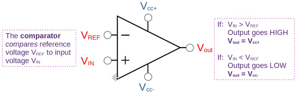
In an op amp comparator, one input is used as a reference voltage (VREF), and the other is used as an input (VIN).
The input signal is compared with the reference signal. If the input signal is greater than the reference, the output will go high. This means that it will saturate at the upper supply voltage, Vcc+.
If the input signal is lower than the reference, the output will go low. In other words, it will saturate at the lower supply voltage, Vcc-.
Non-Inverting and Inverting Op Amp Comparators
There are actually two ways of configuring an op amp comparator circuit. They can be configured as either non-inverting or inverting comparator circuits.
Up to this point, we have seen non-inverting comparators. The functionality of inverting comparators is essentially the same, except the input configuration is reversed. This results in the output also being reversed. Where a non-inverting comparator would output HIGH, an inverting comparator would output LOW and vice versa.
Once we understand the functionality of one configuration, it is easy to understand the other.
Non-Inverting Op Amp Comparator
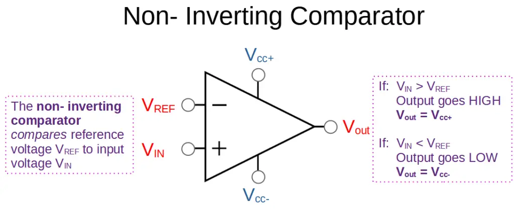
The non-inverting comparator is the most common configuration, and is the example that we’ve already seen. It has the reference voltage VREF on the inverting input and the input voltage VIN on the non-inverting input.
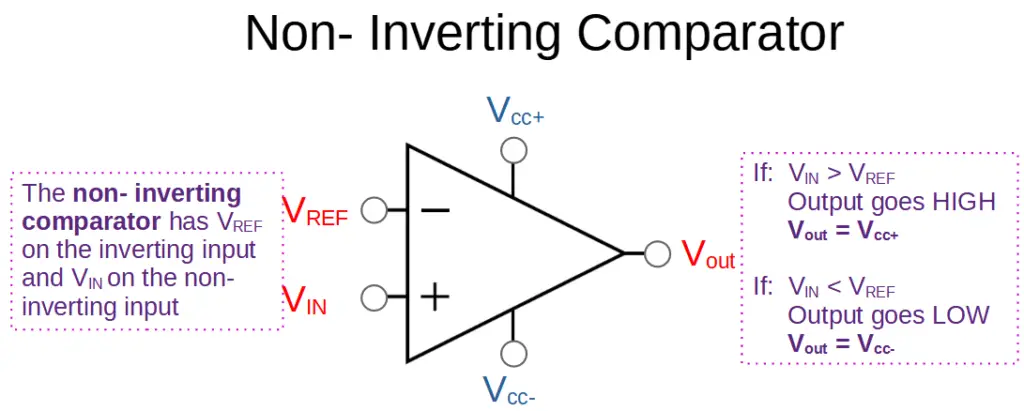
As a result, when VIN is greater than VREF, the output will be HIGH. This corresponds with the logic level 1. When VIN is less than VREF, the output will be LOW. This corresponds with the logic level 0.
| Input | Output |
| VIN > VREF | HIGH (1) |
| VIN < VREF | LOW (0) |
Non-Inverting Op Amp Comparator Examples
The following examples help illustrate the functionality of the non-inverting op amp comparator.
Example 1: Non-Inverting Comparator HIGH
For the first example, we will use a reference voltage (VREF) of 5 volts and an input (VIN) of 5.1V. The power supply voltages will be 15V and 0V (ground):
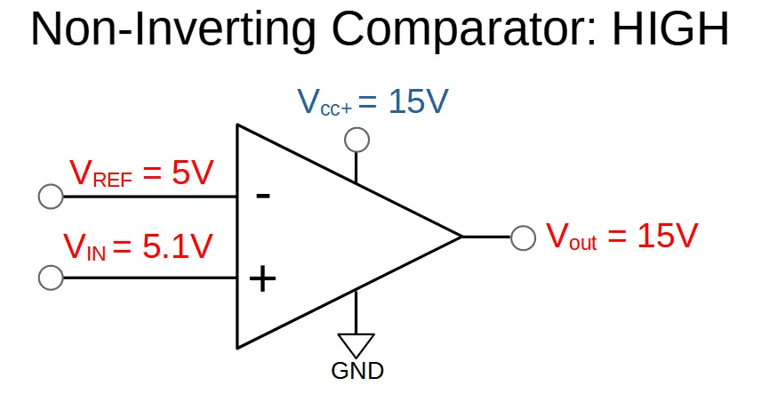
In this case, the voltage on the non-inverting input is greater than the voltage on the inverting input. As a result, the op amp will drive the output high.
Since there is no feedback connecting the output with the inverting input, this increase in the output voltage has no effect on the input side. The op amp will drive the output higher until it saturates at Vcc+, which is 15 volts.
Now let’s see what happens when the input voltage falls below the reference voltage.
Example 2: Non-Inverting Comparator LOW
In this case, the input voltage (VIN = 4.9V) has fallen below the reference voltage (VREF = 5V).
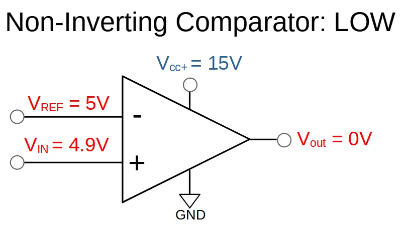
Since the voltage on the non-inverting input to the op amp is below the voltage on the inverting input, the op amp will drive the output down. The output will decrease until it saturates at the lowest possible value that it can achieve.
In this case, Vcc- is connected to ground. This results in an output of 0 volts.
Inverting Op Amp Comparator
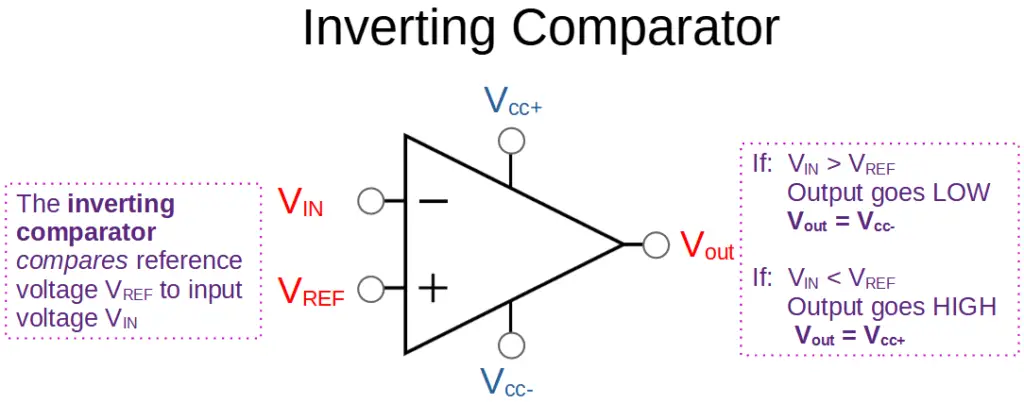
The inverting op amp comparator has the reference voltage connected to the non-inverting input and the input voltage connected to the inverting input. This is the opposite configuration of the non-inverting comparator.
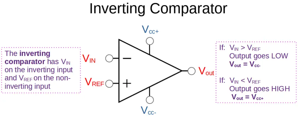
Due to this configuration, when VIN is greater than VREF, the output will be LOW. This corresponds with the logic level 0. When VIN is less than VREF, the output will be HIGH. This corresponds with the logic level 1.
| Input | Output |
| VIN > VREF | LOW (0) |
| VIN < VREF | HIGH (1) |
Inverting Op Amp Comparator Examples
The following examples help illustrate the functionality of the inverting op amp.
Example 1: Non-Inverting Comparator LOW
In this case, the input voltage (VIN) is slightly higher than the reference voltage (VREF).
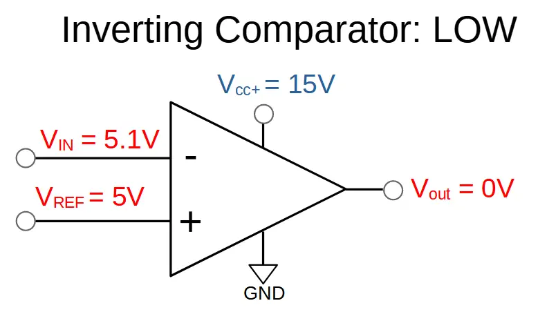
From the perspective of the op amp, the voltage level on the inverting input is greater than the voltage on the non-inverting input. This causes the op amp to lower the output voltage.
Since there is no feedback, the op amp will continue to reduce the output voltage until it saturates at the lowest possible level. In this example, Vcc- is connected to ground, so the output will saturate at 0 volts.
Example 2: Non-Inverting Comparator HIGH
In this example, we reduce the input voltage until it is slightly lower than the reference voltage.
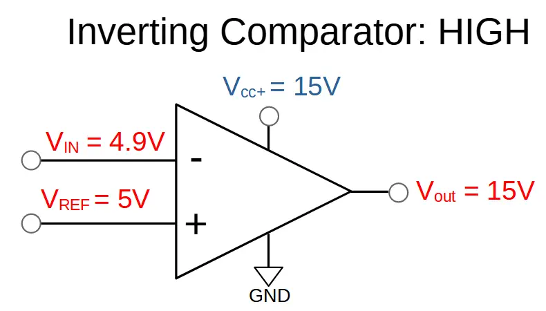
This time, the voltage on the non-inverting input is greater than the voltage on the inverting input. This causes the output of the op amp to increase.
The output increases until it saturates at Vcc+. This means that the output will be 15 V.
Op Amp Comparator With Hysteresis
One of the difficulties in working with op amp comparators can be their sensitivity to noise. Since the output is one of two digital values, noise can result in an unstable output with multiple unwanted output transitions over short periods of time. This can be an issue in many applications, particularly in industrial environments.
In this case, we can use an op amp comparator with hysteresis to help resolve the issue. This can be useful to prevent instability due to noise and capacitive strays from the output to an input. In this configuration, the op amp comparator can be called a hysteresis comparator.
We can create a hysteresis comparator by connecting the output to the non-inverting input via a resistor to restrict the current appropriately.
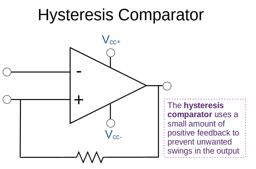
The key is introducing a small amount of hysteresis using positive feedback. This separates the upward and downward going switching points. Once a transition begins, the input must have a significant reversal in order for a reverse transition to occur.
We can think of hysteresis as adding a buffer to the input signal so that the output does not swing wildly due to noise. The input must be high enough, or low enough, over or below the reference point, depending on the configuration, to cause the op amp to switch.
Hysteresis can be used with either non-inverting or inverting op amp comparators.
Op Amp Comparator Truth Table
An op amp comparator can be used a type of logic circuit. As a result, we can construct something like a truth table. However, since the inputs are analog, we must assume that a value of ‘true’ is any value greater than the reference voltage, while ‘false’ is any value below the reference voltage.
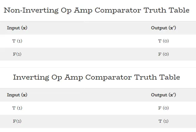
We can see from these truth tables that the logical operation for the non-inverting comparator is trivial. It does not actually perform a logical operation, but instead acts as a type of buffer. In contrast, the inverting comparator acts as a NOT function.
The significance of the op amp comparator is that it will convert a wide range of analog inputs into a digital output. We have to note that this results in a large loss of information; we can’t tell from the output what the actual input was. We only know whether it was above or below a reference signal. A ‘true’ from a non-inverting op amp comparator only tells us that the input was above the reference; we don’t know if it was just above the reference or 100 times greater than the reference.
Non-Inverting Op Amp Comparator Truth Table
| Input (x) | Output (x’) |
| T (1) | T (0) |
| F(1) | F (0) |
We can see that the non-inverting op amp simply passes the logic value from the input to the output; it does not perform a meaningful logic operation.
Inverting Op Amp Comparator Truth Table
| Input (x) | Output (x’) |
| T (1) | F (0) |
| F(1) | T (1) |
The inverting op amp functions as a NOT function. It flips the logic value from true to false or from false to true.
Op Amp Comparator Applications
Op amp comparators are used in many applications. Some of the more common applications are analog to digital conversion, analog signal measurement, and relaxation operators.
Comparators are useful any time we want to send a signal based on some value relative to a reference voltage. For example, they can be used to detect when a battery is running low. They can be used in thermostats to trigger action when the temperature gets too high or low, or in refrigerators to trigger the operation of the refrigeration unit.
Op Amp Comparator IC
One of the most popular op amp comparator integrated circuits is the LM 741 by Texas Instruments. You can find the datasheet here.
The LM741 has excellent performance and features. These include overload protection on both inputs and the output, freedom from oscillations, and no latch-up when the common mode range is exceeded.
However, when designing a circuit it is always best to use the optimal IC available. Although the LM741 is an excellent op amp, there are integrated circuit comparators that are specifically designed for the task of comparing two voltages. The LM741 is a great chip but we are better off using a specifically designed comparator in any production solution.
For comparator specific applications, it is better to use something like the LM397 rather than a general purpose op amp. You can find the datasheet for the LM397 here.