Clamper Circuit
A clamper is a circuit that adds a DC component to an AC signal. This can be used to set the levels of the positive and negative peaks of an AC waveform.
In other words, clamper circuits are used to raise or lower an entire AC voltage waveform.
Clamper circuits function by using a capacitor to store and release electric charge and function as a voltage source in the circuit.
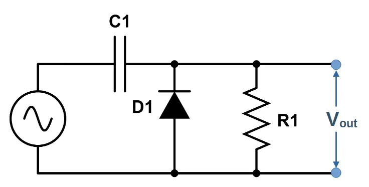
A simple clamper circuit consists of a capacitor, a diode, a resistor, and a primary AC voltage source.
Along with their similar sounding ‘cousins’ clipper circuits, clampers are commonly used to modify AC signals.
What is a Clamper Circuit?
The best way to understand a clamper circuit is to look at what the clamper circuit actually does.
Let’s look at the input and output of a clamper circuit in order to understand its’ function.
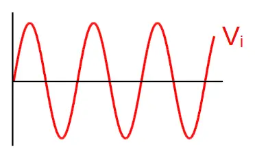
The clamper receives a sinusoidal AC input signal. The input voltage is called Vi. The sine waveform is usually centered around 0V.
We will use the clamper circuit to raise the voltage level of the entire waveform.
Clamper Circuit Input
Clamper Output
The clamper does not distort the voltage waveform in any way. Unlike clipper circuits, clamper circuits don’t flatten any peaks or valleys.
Instead, the entire voltage waveform is shifted up or down by a designated amount. The output voltage is called Vo.
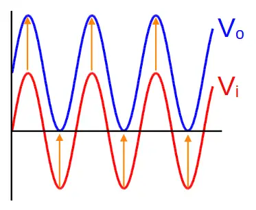
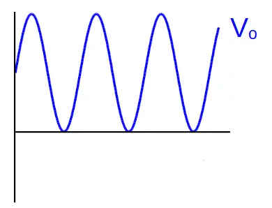
This image shows the output voltage more clearly.
Clamper Time Constant
Like other RC circuits, clamper circuits feature a characteristic time constant ‘τ’, which is equal to value of the resistor times the value of the capacitor used in the clamper circuit:
\tau=RC
This time constant is an indication of the time it takes for the capacitor to charge and discharge. If the time constant is much greater than the frequency of the AC source, the capacitor will function as a voltage source through each cycle. The circuit designer can ensure that the clamper circuit will function properly by increasing time constant (using a larger value resistor or capacitor).
Clamping Voltage
Clamper circuits all feature a clamping voltage. The clamping voltage is the voltage level that the clamper adds or subtracts from the waveform.
The diode in the clamper circuit produces a voltage drop that reduces the clamping voltage.
For example, a clamper circuit
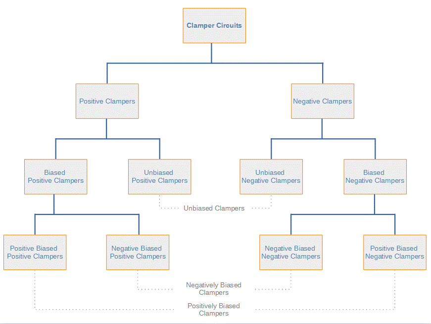
Types of Clamper Circuits
There are several different types of clamper circuits. Here’s a brief overview and then we’ll explore each one in more depth:
Positive and Negative Clampers
The first major division is between positive and negative clamper circuits.
Positive clampers add a positive clamping voltage to the entire waveform.
Negative clampers add a negative clamping voltage to the entire waveform.
Biased and Unbiased Clampers
The next division is between biased and unbiased clampers. Both positive and negative clampers can be either biased or unbiased.
Unbiased clampers use the clamping voltage produced by the capacitor alone.
Biased clampers use an extra voltage source to shift the clamping voltage up or down. They use a capacitor as well as another source, such as a battery. The additional voltage source allows more control in determining the final clamping voltage, enabling the voltage to be adjusted up or down by the battery voltage.
Positive Biased and Negative Biased Clampers
There are two types of biased clampers: positive biased and negative biased.
Positive biased clampers contain a voltage source (like a battery) that adds a positive voltage, shifting the clamping voltage up.
Negative biased clampers have a voltage source that adds a negative voltage, shifting the clamping voltage down.
Positive Clamper Circuits
Positive clamper circuits are used to add a positive clamping voltage to a signal. It increases the voltage of the entire waveform by the clamping voltage.
A positive clamper circuit increases the central voltage level around which the sine wave oscillates by the maximum voltage level of the original sine wave, Vm. It shifts the entire voltage waveform up by Vm.
Positive clamper circuits are divided into two main categories: unbiased positive clampers, and biased positive clampers. Biased positive clampers can also be divided into clamper circuits with positive bias and clamper circuits with negative bias.
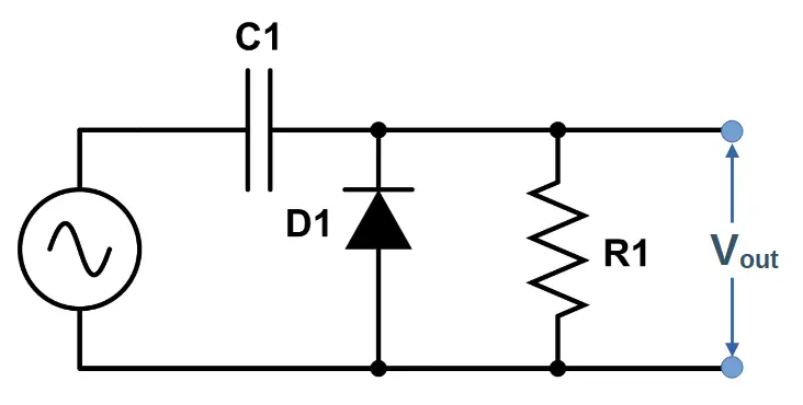
Unbiased Positive Clamper
An unbiased positive clamper has a positive clamping voltage and uses the combination of a diode and capacitor.
Unbiased Positive Clamper Circuit Diagram
It may be helpful to review our lesson on capacitors in AC circuits.
The clamper circuit does not function during the first positive half cycle because the diode is reverse-biased.
Instead, the capacitor will charge during the first negative half cycle, while the diode is forward biased.
Once the capacitor is charged, it will then discharge during subsequent cycles, adding a positive voltage to the entire waveform.
The capacitor will maintain the voltage placed on it, and will be successful as long as the period of the waveform is much less than the RC time constant τ.
It will then produce a voltage equal to the maximum value of the input waveform, Vmax. This voltage is added to the whole waveform, thereby boosting the voltage level of the entire AC signal.
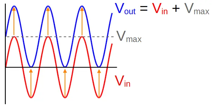
The original signal Vin was centered around zero and had a maximum voltage (peak voltage) of Vmax.
In contrast, the output of the unbiased positive clamper circuit is now centered around Vmax, and has a maximum peak voltage of 2Vmax.
The equation describing the output voltage waveform is:
Vout = Vin + Vmax
Biased Positive Clampers
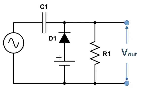
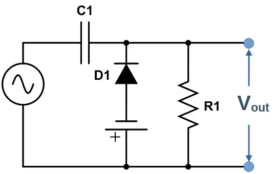
Positive Biased Positive Clamper
Positive biased clampers add a voltage source (like a battery) to the circuit. Take note of the orientation of the voltage source; the positive terminal faces the capacitor.
Positive Biased Positive Clamper Circuit Diagram
The battery adds voltage Vbias to the whole voltage waveform, as we can see in the figure below:
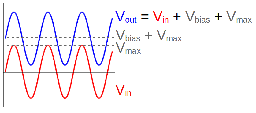
The output of this circuit is equal to the input Vin, plus the battery voltage Vbias, plus the capacitor voltage Vmax:
Vout = Vin + Vbias + Vmax
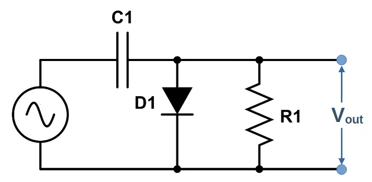
Negative Biased Positive Clamper
Negative biased clampers also have a voltage source, but it is used in the opposite orientation as the source in a positively biased clamper.
Negative Biased Positive Clamper Circuit Diagram
In this case, the battery adds a negative voltage Vbias to the whole voltage waveform, as we can see in the figure below:
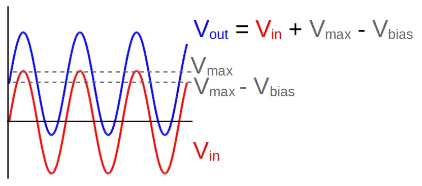
The output of this circuit is equal to the input Vin, plus the capacitor voltage Vmax, minus the battery voltage Vbias, :
Vout = Vin + Vmax – Vbias
Negative Clamper Circuits
Negative clamper circuits are used to add a negative clamping voltage to a signal. In essence, a negative clamper circuit decreases the central voltage level around which the sine wave oscillates.
Negative clamper circuits are also divided into two categories: unbiased negative clampers, and biased negative clampers. Biased negative clampers can also be divided into negative clamper circuits with positive bias and negative clamper circuits with negative bias.
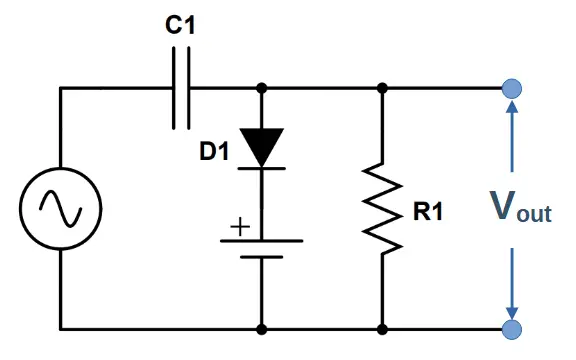
Unbiased Negative Clamper
An unbiased negative clamper has a negative clamping voltage and uses the combination of a diode and capacitor.
Unbiased Negative Clamper Circuit Diagram
The capacitor will maintain the voltage placed on it, and will be successful as long as the period of the waveform is much less than the RC time constant τ. The right side of the capacitor will charge during the first positive half cycle, while the diode is forward biased.
It will then produce a voltage equal to the negative maximum value of the input waveform, -Vmax. This voltage is added to the whole waveform, thereby lowering the voltage level of the entire AC signal.
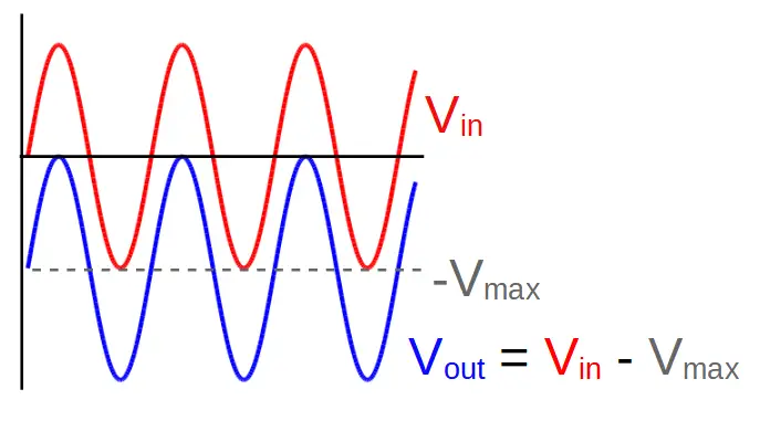
The original signal Vin was centered around zero and had a maximum voltage (peak voltage) of Vmax.
In contrast, the output of the unbiased negative clamper circuit is now centered around -Vmax, and has a negative peak (i.e. lowest point of the ‘valley’) voltage of -2Vmax.
The output of this circuit is the input voltage Vin, plus the negative voltage contributed by the capacitor -Vmax:
Vout = Vin – Vmax
Note that we stated this as ‘plus the negative voltage -Vmax‘ instead of ‘minus Vmax‘. This is because a more complex signal might have different absolute values for the top of the most positive peak and the most negative valley. We differentiate by calling -Vmax the lowest point of the waveform instead of just assuming that |Vmax| = |-Vmax|.
Biased Negative Clampers
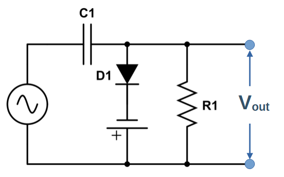
Positive Biased Negative Clamper
Positive biased clampers add a voltage source (like a battery) to the circuit. Take note of the orientation of the voltage source; the positive terminal faces the capacitor.
Positive Biased Negative Clamper Circuit Diagram
The battery adds voltage Vbias to the whole voltage waveform.
Even though the capacitor adds a negative voltage -Vmax, the battery adds a small positive voltage Vbias, allowing the clamper circuit to output a signal that is below the input Vin, but not quite as low as an unbiased negative clamper. We can see this in the figure below:
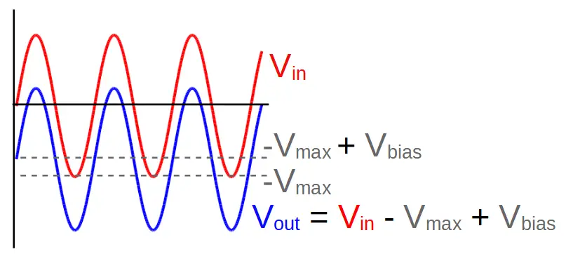
The output of this circuit is equal to the input Vin, plus the negative capacitor voltage -Vmax, plus the battery voltage Vbias:
Vout = Vin – Vmax + Vbias
Negative Biased Negative Clamper
Negative biased clampers also have a voltage source, but it is used in the opposite orientation as the source in a positively biased clamper.
Negative Biased Negative Clamper Circuit Diagram
In this case, the battery adds a negative voltage Vbias to the whole voltage waveform, as we can see in the figure below:
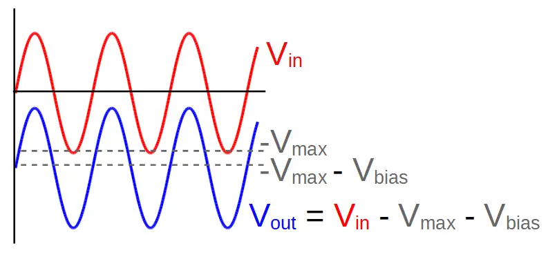
The output of this circuit is equal to the input Vin, plus the capacitor voltage Vmax, minus the battery voltage Vbias, :
Vout = Vin + Vmax – Vbias