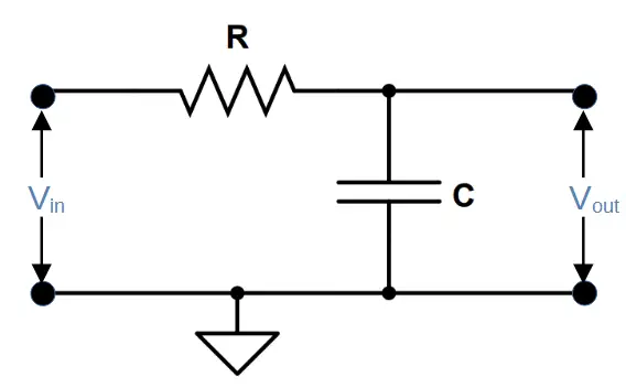
A low pass filter is a type of filter circuit that is used to attenuate frequencies above a cut-off frequency fC.
They consist of a resistor and capacitor in series, with the output taken across the capacitor.
The following calculators are designed to aid in the design and understanding of low pass filters.
There are three calculators on this page:
1) Low pass filter cut-off frequency calculator
2) Low pass filter capacitor selection calculator
3) Low pass filter resistor selection calculator
Low Pass Filter Cut-Off Frequency Calculator
The low pass filter cut-off frequency calculator can be used to calculate the cut-off frequency. Two inputs are required: (1) the resistance of R1, and (2) the capacitance of C1. Based on these values, the calculator will provide the cut-off frequency.
The mathematical formula for the cut-off frequency in terms of the resistance of R1 and capacitance of C1 is given by:
f_C = \frac{1}{2 \pi R_1 C_1}Low Pass Filter Capacitor Selection Calculator
The low pass filter capacitor calculator can be used to calculate the value of capacitor needed to create a filter with a specific cut-off frequency.
It requires two inputs: (1) the desired cut-off frequency, and (2) the resistance of R1.
The mathematical relation for the capacitance of C1 in terms of the cut-off frequency fC and resistance of R1 is given by:
C_1 = \frac{1}{2 \pi f_C R_1}Low Pass Filter Resistor Selection Calculator
The low pass filter capacitor calculator can be used to calculate the value of resistor needed to create a filter with a specific cut-off frequency.
It requires two inputs: (1) the desired cut-off frequency, and (2) the capacitance of C1.
The mathematical relation for the resistance of R1 in terms of the cut-off frequency fC and capacitance of C1 is given by:
R_1 = \frac{1}{2 \pi f_C C_1}If these calculators didn’t help, check out our other calculators for electronics or our comprehensive tutorials!