Low Pass Filter
Filters are circuits that are used to remove part of a complex AC signal.
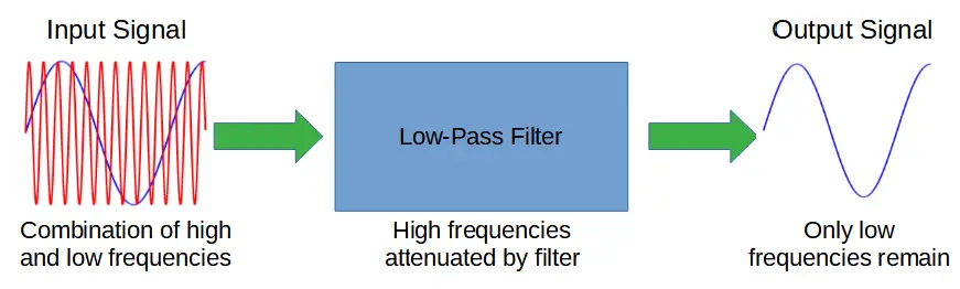
A low pass filter is designed to remove unwanted high frequencies from a complex input signal. An ideal low pass filter would pass only frequencies lower than a cut-off frequency.
The process of removing unwanted frequencies is called attenuation. A low pass filter primarily attenuates high frequencies so that the resulting output is comprised of only low frequencies.
Low-pass filters don’t create any of the frequencies they output; they simply eliminate high frequencies, leaving only the desired low frequencies.
In the case of active low-pass filters, an amplifier is used to increase the strength of the low frequency signal. The fundamental operation of the filter (attenuating high frequencies) remains the same as a passive low-pass filter.
Low-pass filters require capacitive reactance in order to work. They take advantage of the fact that a capacitor’s impedance to an alternating current (AC) source scales with frequency.
Low pass filters are often compared with high pass filters, which also features a resistor and capacitor in the opposite configuration to remove low frequencies from an AC signal.
Comprised of a resistor and capacitor, the cut-off frequency of a filter is determined by the values (i.e. resistance and capacitance) of the two components.
Low-pass filters rely on the phenomenon of AC impedance in order to function. Impedance is the opposition to flow of current in AC circuits. In DC circuits, only resistance opposes current but in AC circuits, the flow of electric current is also opposed by capacitors and inductors.
In AC circuits, resistors contribute resistance, just like they do in DC circuits. Capacitors contribute capacitive reactance, which depends on the frequency of the input AC signal. The total impedance is the sum of the resistance and reactance.
Impedance = Resistance + Reactance
Low pass filters take advantage of capacitive reactance, which is frequency dependent. The characteristic cut-off frequency of the low pass filter is due to the values of both the resistor and capacitor.
Ideal Low Pass Filter
A low pass filter preferentially attenuates high frequencies, so that low frequencies are allowed to pass while high frequencies are blocked.
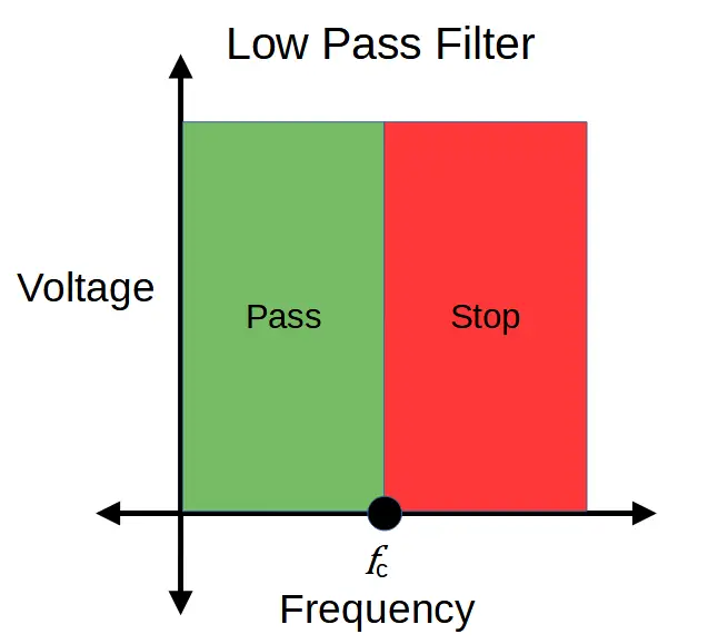
An ideal low pass filter would prevent any frequency component above the cut-off frequency fc from passing, but real-life low pass filters aren’t perfect.
Both high and low pass filters use a combination of resistor and capacitor, but the arrangement is reversed in each. A low pass filter has the input signal applied directly to the resistor, and the output is measured across the capacitor:
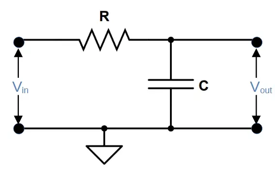
A low pass filter therefore consists of a resistor and capacitor in series.
The input waveform Vin is passed through the resistor, and the output waveform Vout is measured across the capacitor.
The fact that the output is measured across the capacitor is crucial to the functionality of the filter. It means that the output of the filter is equal to the voltage drop (i.e. potential difference) across the capacitor.
The filter works because the voltage dropped by the capacitor depends on its’ capacitive reactance, which is frequency dependent.
Capacitive Reactance in Low-Pass Filters
The overall characteristics of the low pass filter comes from the interplay of capacitive reactance and resistance, which both contribute to the total impedance.
The impedance contributed by the resistor (i.e. resistance) doesn’t depend on the frequency, but the capacitive reactance XC is inversely proportional to the frequency f:
X_C = \frac{1}{\omega C} = \frac{1}{2\pi fC}This means that at low frequencies the capacitive reactance is high while at high frequencies, the capacitive reactance is low.
Capacitive Reactance vs. Frequency
A plot of capacitive reactance vs. frequency illustrates how the voltage drop across the capacitor changes with frequency:

At low frequencies, the voltage drop across the capacitor is very high.
The output is measured across the capacitor, so the output voltage will also be very high when the frequency is low. This allows low frequencies to pass through the filter, hence the name ‘low pass filter’.
The capacitive reactance rapidly drops off so that a small increase in frequency leads to a much larger decrease in reactance (i.e. impedance).
At high frequencies the capacitive reactance is low, so most of the voltage is dropped by the resistor. The voltage drop across the capacitor is low. If we measure the voltage output across the capacitor, the signal strength will be extremely low.
This means that the high frequency component in the output will be small.
Low-Pass Filter Output vs. Frequency
We can confirm this result by plotting the output voltage against frequency, as you can see in the image below:
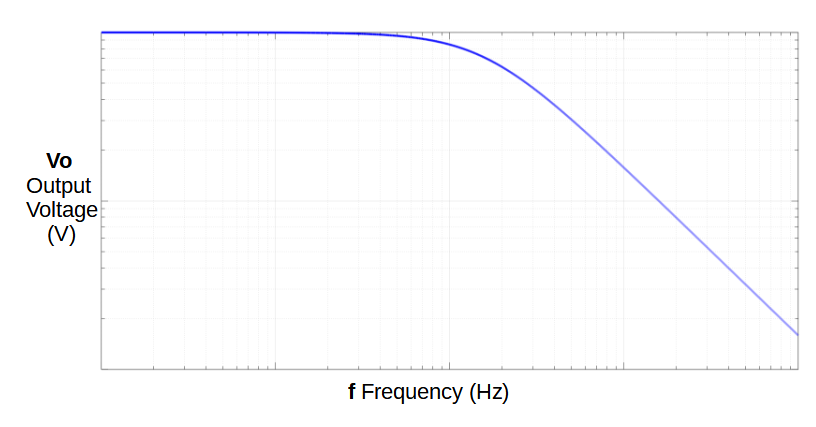
As we can see, the output voltage remains high at low frequencies.
At high frequencies, the output quickly approaches zero.
We can also see that real-life low pass filters are not ideal; an ideal low pass filter would have a vertical line at the cut-off frequency. Instead, high frequencies are significantly reduced in power but not removed entirely.
If we were to magnify the curve at low frequencies, we would also see that low frequencies are not allowed to pass perfectly; every frequency experiences some attenuation. The total attenuation is far smaller at low frequencies than it is at high frequencies.
Low Pass Filter Cut-Off Frequency
The cut-off frequency fc can be determined by the values of the resistor and capacitor.
f_c = \frac{1}{2 \pi R C}Accordingly, one can determine the value of resistor or capacitor to construct a low pass filter by solving for any value given the others.
Solving Low Pass Filter Problems
To find the value of a resistor given the required cut-off frequency and value of capacitor:
R = \frac{1}{2 \pi f_c C}To find the value of a capacitor given the required cut-off frequency and value of resistor:
C = \frac{1}{2 \pi f_c R}Mathematical Description of Low Pass Filter
At low frequencies, the capacitive reactance of the circuit will be high compared with the resistance contributed by the resistor.
We can therefore think about this circuit as a type of tunable voltage divider. Recall the voltage divider formula:
V_{out} = V_{in} \frac{R_2}{R_1 + R_2}=V_{in} \frac{R_2}{R_T}If we substitute capacitive reactance XC and impedance Z into the formula for the voltage divider, we find the following relation:
V_{out}=V_{in} \frac{X_C}{Z}Where Z is the total impedance and Xc is the capacitive reactance. The relation between the impedance and reactance is given by:
Z = \sqrt{R^2 + X_C^2}If we solve for the output while varying the frequency, we find that low frequencies have a significantly higher output than higher frequencies:
The relation for Vout can be found by substituting the formula for impedance (Z) into the relation between Vin and Vout:
V_{out}=V_{in}\frac{X_C}{\sqrt{R^2 + X_C^2}}This is shown in the plot of Vout, which we saw earlier.
Summary of Low-Pass Filters
We have seen that low-pass filters rely on capacitive reactance in order to generate a high voltage across the capacitor at low frequencies. By configuring the output as the voltage across the capacitor, the low-pass filter ingeniously makes use of the capacitor’s tendency to block low frequencies.
It’s important to keep in mind that while an ideal low-pass filter would block all frequencies above the cut-off frequency, actual low-pass filters block all frequencies to some degree. This is why amplifiers are often employed after the filter stage. The combination of filter and amplifier is often known as an active low-pass filter.