Series vs. Parallel Circuits
Electrical circuits can be set up by placing components in series, in parallel, or in a combination of the two. Series circuits offer a single current path, while parallel circuits offer multiple paths for current to follow.
A series circuit has only one path for current to follow. Within the circuit, there is no ‘branching’ or separate paths. If you were to trace the flow of current, there would therefore be only a single path through the circuit. The current is the same for all components in a series circuit. The current is defined by the total resistance in the circuit, and can be determined by using Ohm’s Law.
A parallel circuit offers current more than one path to follow. This means that at some point the circuit ‘branches’, causing multiple paths for current to follow. This can occur at any point in the circuit; the current may split and then recombine later in the circuit. In parallel circuits, current will flow through all available paths, with more current going through paths with less resistance. Wherever multiple current paths exist, the voltage will be the same across all paths.
Circuit components (also called circuit elements) are the devices that make a circuit, such as resistors, capacitors, inductors, diodes, or transistors.
Components can be connected in series, parallel, or in a combination that is sometimes referred to as series-parallel.
These three configurations make up all electrical circuits.
The first step to understanding electric circuits is being able to recognize when components are in series, parallel, or a combination, as well as the effect these configurations have on the circuit itself.
One of the most important things to remember is that every component behaves differently when arranged in series versus parallel. There are rules for solving series circuits, as well as rules for solving parallel circuits.
In this module, we’ll learn about resistors, capacitors, and inductors in series, parallel, and series-parallel configurations.
Let’s continue our introduction with a brief overview on what these terms actually mean.
Series vs. Parallel Circuits
Throughout this course, we will see examples of how to solve problems that are increasing in complexity and learn how to understand and use some of the most important types of circuits.
Let’s take a closer look at series and parallel circuits.
Series Circuits
A series circuit is formed when components are connected via a single conductive path with each other. In the circuit diagram below, two components called resistors (R1 and R2) are connected in series with each other to complete the circuit. Resistors are simply components that provide a defined amount of electrical resistance to any current that passes through them.
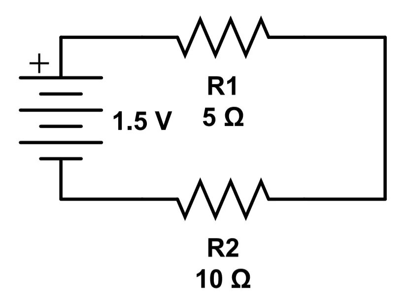
We can see that R1 and R2 are connected to form a single conductive path. Electric current flows from the positive terminal of the battery, through R1 and R2, to the negative terminal of the battery. The current through all components is the same.
The current through the entire circuit is determined by the resistance of each component.
Parallel Circuits
A circuit that is made of components connected in parallel is called a parallel circuit. Components are connected in parallel if they are connected by multiple conductive paths. This means that the current has a ‘choice’; it has more than one place to go. Here’s a simple example of two resistors connected in parallel:
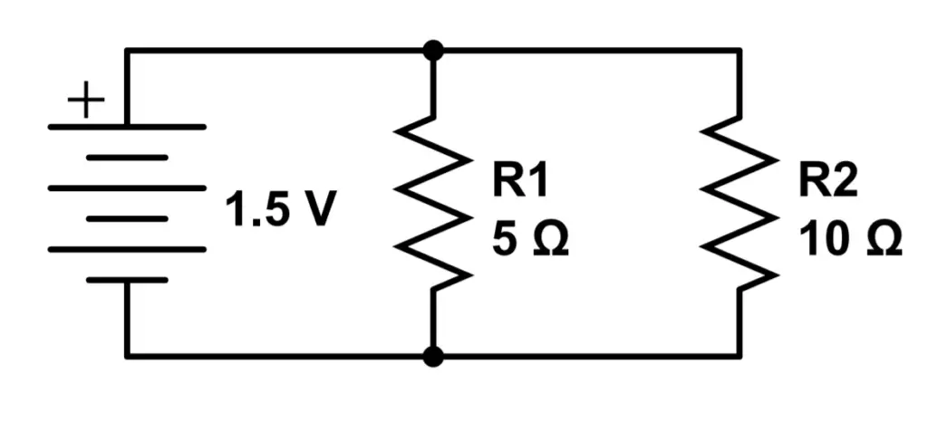
On the left side of the circuit, we can see a three cell battery supplying 1.5 Volts to the circuit.
The current leaves the battery at the positive terminal and reaches the first junction.
Some of the current goes down through R1, a 5 Ohm resistor. Some of the current does not go through R1 but instead goes through R2, a 10 Ohm resistor.
In other words, current flows through both R1 and R2 simultaneously. The current then continues to travel toward the negative terminal of the battery.
Yet the current is different in each path. Current always follows the path of least resistance. The higher the resistance, the less current will flow through a certain path.
In the above circuit, R1 has a resistance value of 5 Ohms, whereas R2 offers a resistance of 10 Ohms. Since R1 has half the resistance of R2, the current through R1 will be twice the current through R2. We don’t need to calculate the actual current to determine this; no matter the voltage supplied by the battery, the current through R1 will always be twice the current through R2 because R1‘s resistance is half that of R2.
However, the voltage is the same for each path in this circuit. The conductors on the positive side of the battery are all connected, as are the conductors on the negative side. So the voltage difference between the two sides is just the voltage of the battery, which is 1.5 volts in this case.
We’ll learn how to analyze resistors in parallel in a few lessons.
Series-Parallel Circuits
Many circuits are more complex than pure series or parallel circuits.
It is common to find circuits that have both series and parallel components. These are called series-parallel circuits.
For example, the circuit below shows resistors in both series and parallel, forming an interesting series-parallel circuit.
In this case, there is a parallel section of the circuit that is ‘nested’ in between series components.
Can you tell which resistors are in parallel and which are in series?
Current must pass through both R1 and R4 but it has a choice regarding whether or not to go through R2 or R3. Therefore R1 and R4 are in series, while R2 and R3 are in parallel.
Here’s another example.
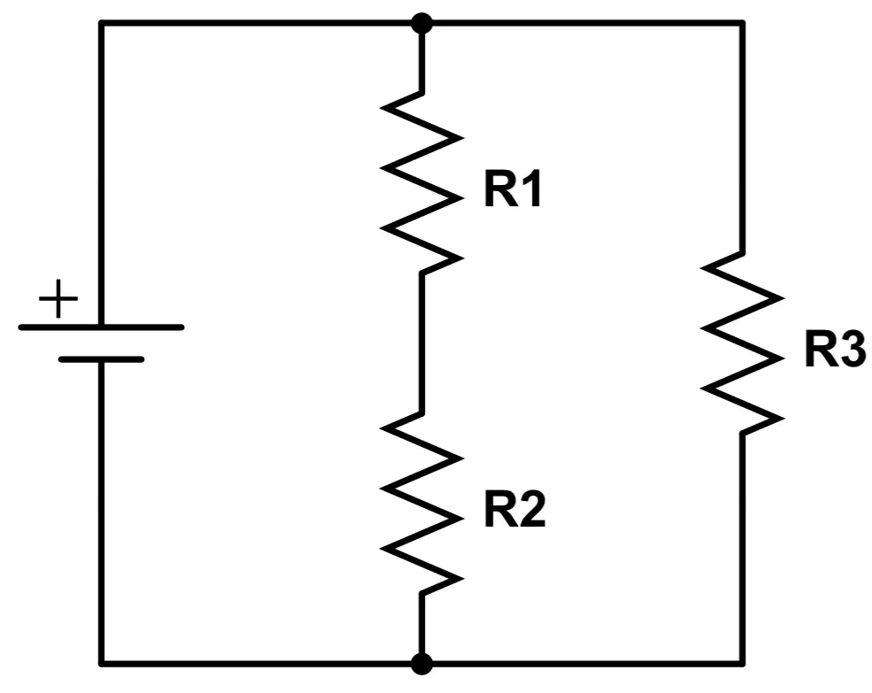
This time, the circuit has a section that is in series nested within a parallel branch. R1 is in series with R2 but both are in parallel with R3.
In all of these cases, the circuit diagram shows us how current travels through the circuit.
However, the actual attributes of the circuit depend on what type of components are used and their attributes.
For example, the same rules cannot be applied for resistors and capacitors in circuits; resistors in series increase total resistance but capacitors in series decrease the total capacitance. Each component needs to be analyzed on its’ own, which we will learn how to do throughout this module.
Complex circuits can seem intimidating at first. Luckily, almost all systems can be analyzed with some patience and strategy. Many branches or parallel sections of circuits can be easily analyzed by calculating ‘equivalent values’ which represent the total effect of that branch or circuit.
In general, the order of operations for complex circuits is to work from the inside to the outside. Start with the most nested sections, resolve those, and then work your way to the outer ‘layer’ of the circuit one step at a time.
- Resolve all parallel branches first. If those branches contain branches of their own, start with the embedded (i.e. deepest level) branch or components first.
- Calculate whole circuit values using any series elements in combination with the equivalent values from all parallel branches.
For now, the most important thing is simply to gain an understanding of what we mean when we call a circuit series or parallel. To recap:
Series circuits offers only one path for current.
Parallel circuit offers multiple paths for current.
Many circuits have sections that are connected in series, and others in parallel.
Components behave differently depending on their arrangement within the circuit.
Let’s look at our first real circuit components: DC power sources and batteries.
Module 3 – DC Circuits