LC Filter
An LC filter uses a combination of an inductor and capacitor to improve the waveform quality of an electronic signal. LC filters combine the attributes of both inductor filters and capacitor filters, improving the output quality to a greater extent than either individually.
In this article, we will cover LC Filters to improve the output of rectifiers. We will learn about the uses of an LC filter, operational theory, and application in power supplies. LC filter circuits are also used in low-pass, high-pass, band-pass, and band-stop filter applications.
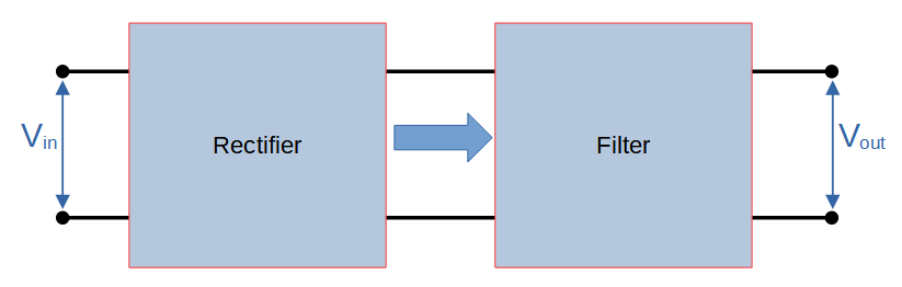
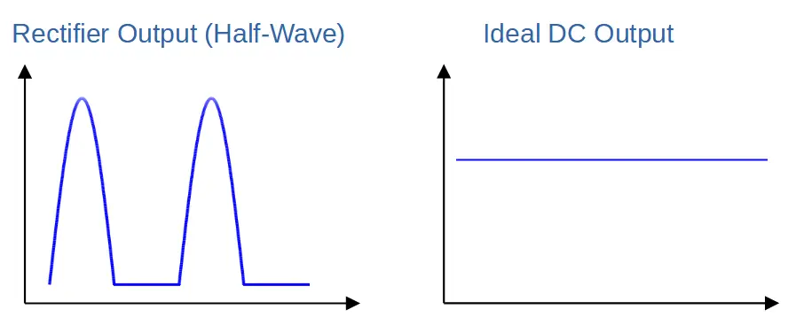
The most common way to convert an AC signal into DC is by using a rectifier. A rectifier is a circuit that takes a sinusoidal AC input and outputs a pulsed DC waveform using diodes. This is an important step in AC-DC conversion, but common electronic devices require a steady, flat DC signal. We need a way to flatten out the pulsed DC waveform.
This is where filters come in. Filters can be used after rectification in order to improve the quality of the output signal.
Inductors and capacitors can both be used as filters, both individually and in combination with each other. Higher quality filters can feature multiple stages involving inductive and capacitive elements to carefully filter the output.
In our previous tutorials on inductor filters and capacitor filters, we learned that each type of filter improves the signal quality, and that they do so in different ways.
LC Filter Circuit
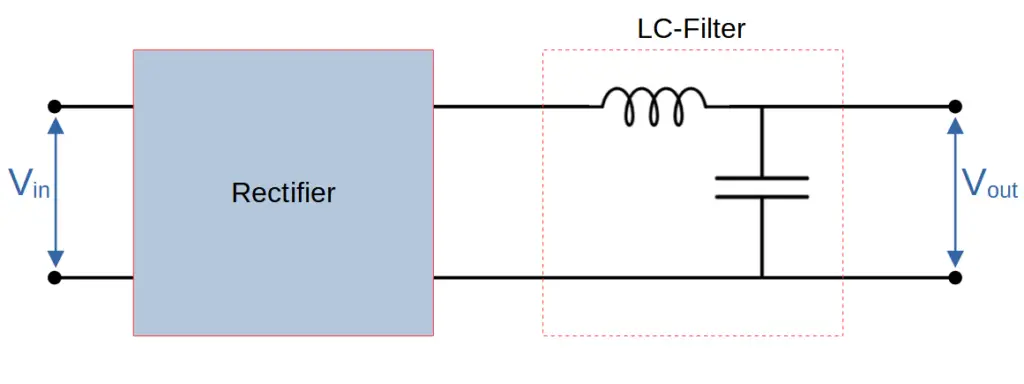
An LC-filter is constructed by combining an inductor in series with the load, and a capacitor in parallel with the load. We can think of this filter has having two stages; an inductor stage and a capacitor stage.
LC Filter Circuit Diagram
Stage One: Inductor
The inductor acts as a ‘choke’ for the AC component of the output waveform of the rectifier, and works like an inductor filter.
It allows the DC component to flow through it without attenuation from inductive reactance . However the AC component experiences an impedance due to the inductive reactance (XL) that is proportional to the frequency of the signal as well as the strength of the inductor:
X_L = 2\pi fL
This means that higher frequencies are attenuated more than lower frequencies. Inductors are therefore excellent at reducing the impact of higher-order harmonics.
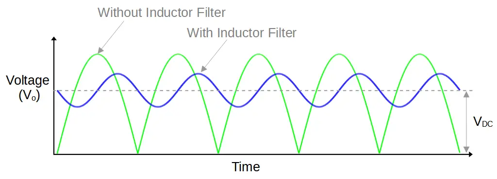
The product of an inductor filter is shown on the right. It produces a sine wave DC signal that oscillates around the average voltage (VDC) output of the rectifier.
We can see that the inductor improves the waveform by preventing the large voltage swings of the full DC pulse.
However, the signal can be further improved by incorporating a capacitor. That’s the difference between an inductor filter and LC filter.
Stage Two: Capacitor
A smoothing capacitor allows the AC component of the signal to pass to ground while blocking the DC current. It also stores and releases electrical energy, providing DC voltage and current through the load when the input waveform would otherwise fall and rise dramatically. It therefore functions as a capacitor filter.
The capacitive reactance (attenuation) is highest at low frequencies:
X_C = \frac{1}{2\pi fC}This means that lower frequencies (and DC) do not pass through the capacitor; instead, they continue on through the load.
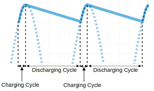
Capacitors improve the waveform in a unique way. They store charge while the voltage exceeds the voltage across the capacitor, and then generate a voltage when the waveform would dip below the voltage they produce.
The output of a capacitor filter (on its’ own, not in an LC filter) is shown on the right. The capacitor smooths the voltage output during its’ discharge cycle. Note that the image shows the effect of a capacitor filter on a half-wave rectifier in order to add clarity (by spacing out the charging and discharging cycles).
LC filters take combine these properties by incorporating inductors and capacitors into one filter.
LC Filter Output
When the capacitor filter is added to the inductor filter to form an LC filter, the output waveform is essentially the resultant from a two stage filter.
This output is shown graphically in the following image:
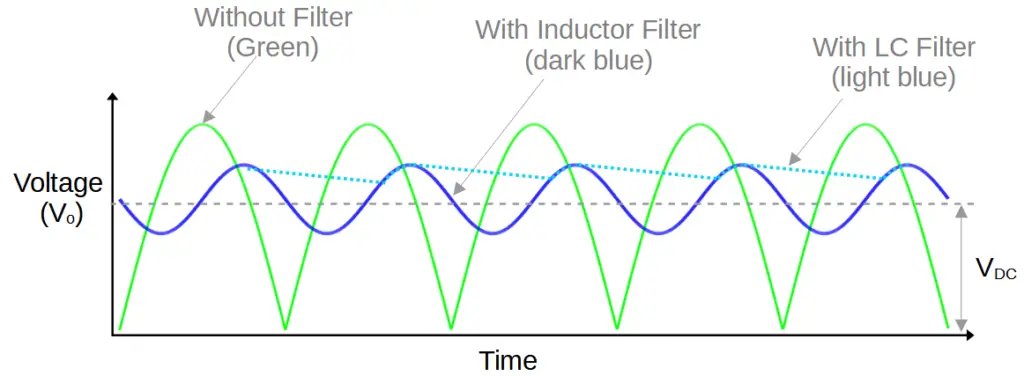
The green line shows the output of a full-wave rectifier, i.e. stage zero (0).
The dark blue line shows the output of the inductor filter, i.e. stage one (1).
The dashed light blue line shows the output of the LC filter, stage two (2). This is the output of the LC filter.
For clarity, the following image shows only the final output:

We can now clearly see that the LC filter dramatically improves the output of either the inductor or capacitor filters alone.
Higher Order LC Filters
In real life applications, LC filters are often cascaded in series in order to produce filters of superior quality.
A filter with two cascaded LC filters would be known as a 2nd order filter. Adding a third filter would result in a 3rd order filter, and so on.
Each stage adds cost but improves the output of the rectifier.
One of the most common versions is known as the pi filter, which uses one more capacitor than a standard LC filter.
Other Types of LC Filters
Like the capacitor and inductor filter, LC filters are used as integral components of many different types of filter circuits. These include low-pass, high-pass, band-pass, and band-stop filters.