Inductor Filter (L-Filter)
An inductor filter, also known as a choke filter, is a circuit that uses an inductor to improve the output signal of a rectifier.
It’s helpful to think of a rectifier as producing a combination of both DC and AC components.
An ideal AC to DC converter would output a signal with no (zero) AC component and 100% DC component.
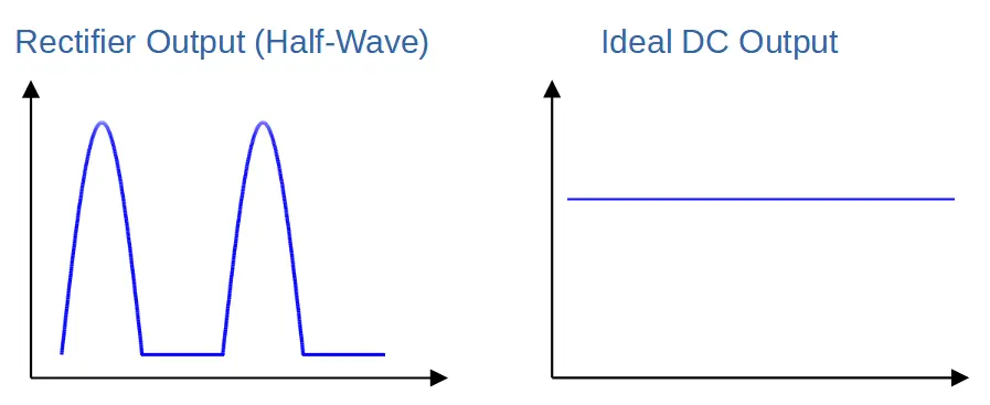
In comparison, rectifiers produce a pulsed DC output that has relatively poor characteristics. This seems obvious because a pulsed signal does not bear much resemblance to a flat DC signal, but it is also reflected in properties like a high ripple factor. This indicates that the AC component within the output signal is large.
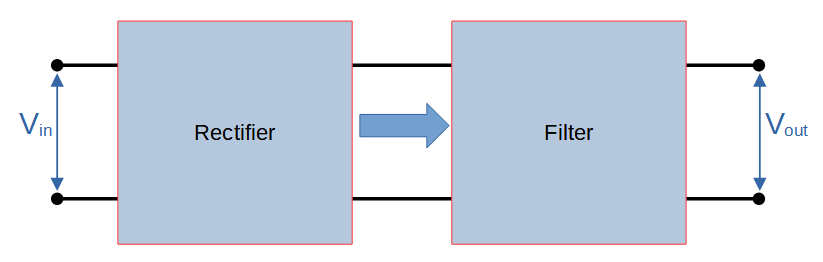
Rectifier filters such as an inductor, or L-filter, are used to improve the output of a rectifier by reducing the AC component and increasing the DC component.
Filters are commonly made from passive components including capacitors and inductors.
Even a single component that is well chosen for the application can drastically improve the output signal quality.
Inductor filters can be used to improve the output quality of half-wave, full-wave, or bridge rectifiers. However the best output signal will be achieved by combining a filter with a rectifier that produces a full output wave such as full-wave and bridge rectifiers.
L-Filter Circuit
An L-filter circuit is constructed by placing an inductor in series with the load.
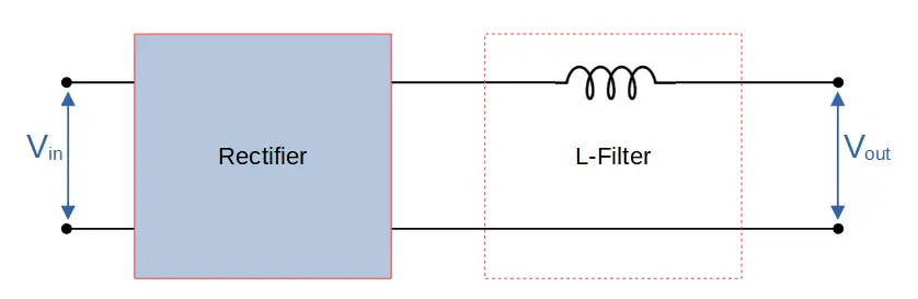
This means that the output signal passes directly through the inductor. Any voltage that is dropped across the inductor will therefore not be measured by the load (Vout).
Since inductors operate by opposing any change in voltage, the inductor will only oppose the AC component of the rectifier’s output.
The DC component is allowed to flow like a short circuit, without any attenuation by the inductor.
The AC component, however, is impacted significantly by the inductor. The inductor introduces impedance to the flow of AC called inductive reactance.
Inductor Filter (L-Filter) Circuit Diagram
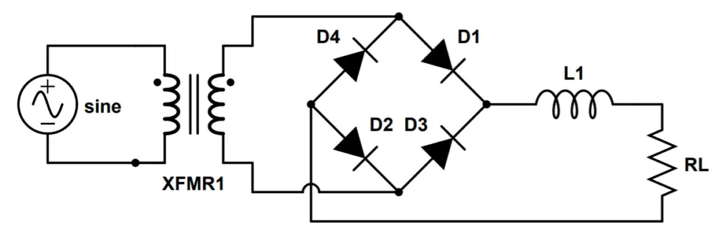
This complete circuit includes an AC source input, step-down transformer, diode bridge rectifier circuit, inductor filter, and a resistive load.
The signal goes through multiple changes as it passes through the circuit:
The transformer (XFMR1) reduces the voltage of the signal to the desired level. It outputs a full sine wave.
The bridge rectifier produces a pulsed DC signal; the negative half-cycles of the sine wave from the transformer are inverted so that the current only travels in one direction.
The L-filter then improves the output of the bridge rectifier by using an inductor to smooth out the waveform.
How an L-Filter Works
Inductor filters operate based on the principle of inductive reactance, which is the opposition to an AC current by an inductor.
Inductive reactance (XL) is measured in Ohms, and is proportional to the frequency of the AC signal as well as the inductance of the inductor:
XL = ωL = 2πfL
This means that higher frequencies are attenuated more highly by the inductor; lower frequencies are attenuated less.
However, all AC frequencies are attenuated by some degree so that the ratio of the DC component of the output to the AC component can be significantly improved even though some AC signal is still allowed to pass. A larger inductor can also be used to remove more of an AC signal, which can be useful when trying to attenuate low frequencies.
With the load modeled by the load resistor RL, the combination of the inductor and load resistor in series functions as a voltage divider for the AC components.
If the inductance and/or frequency are sufficiently high, or the load resistance is small, then the inductive reactance of the inductor will be much greater than the resistance of the load:
XL = ωL >> RL
How An Inductor Filter Improves Signal Quality
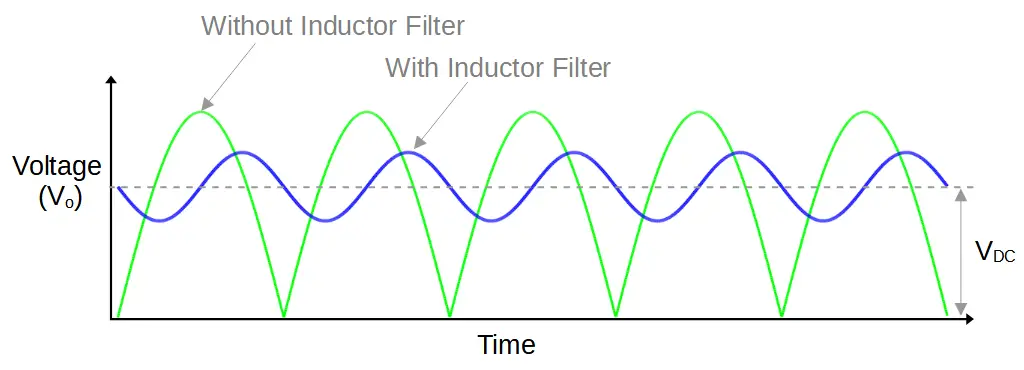
The inductor doesn’t simply provide impedance to AC signals; it stores and releases energy in a magnetic field that opposes the change in voltage. This means that when the voltage to the inductor starts to decrease, it releases energy and generates a voltage that limits the decline in voltage. When the voltage starts to increase, the inductor again generates a voltage, this time limiting the maximum voltage.
The result is that the output of the inductor filter resembles a sine wave with a much lower maximum and greater minimum than the pulsed output it receives. This wave is boosted by the DC component of the voltage VDC, so the final output is a relatively small sine wave centered around VDC.
Even though the waveform is sinusoidal, it does not change direction (i.e. cross the 0/x-axis). The output is a sinusoidal with a changing magnitude but the direction of the current is always ‘forward’ because the voltage is always positive.
In our lessons on full-wave and bridge rectifiers, we calculated that VDC is proportional to the maximum input voltage:
V_{DC} = \frac{2V_m}{\pi}Inductor Filter (L-Filter) Ripple Factor
As in other circuits, the ripple factor is the ratio of the RMS (root mean square) value of the AC component to the RMS value of the DC component of the output signal. It is an indication of signal quality; the higher the ripple factor, the larger the AC component is with regards to the DC component.
The ripple factor is abbreviated by the Greek letter gamma (γ):
\gamma = \frac{I_{rms}'}{I_{DC}}In an inductor filter, the ripple factor depends on the circuit and signal properties. Load resistance, signal frequency, and inductance all play a role in increasing or decreasing the ripple factor. This makes sense because the inductive reactance in the circuit, which plays a major role in ripple factor, depends on both the inductance and frequency.
The ripple factor of a full-wave or bridge rectifier with an inductor filter is:
\gamma=\frac{R_L}{3\sqrt2\omega_0L}The ripple factor can be found by performing a Fourier analysis.
When to Use an Inductor Filter
Inductor filters are particularly useful when the frequency of the AC signal is high or the load resistance is low. In other words, when the inductive reactance is high.
We will also see that inductors can be combined with capacitors to make significantly more effective filters that work over a larger range of frequencies.