Inverting Op Amp
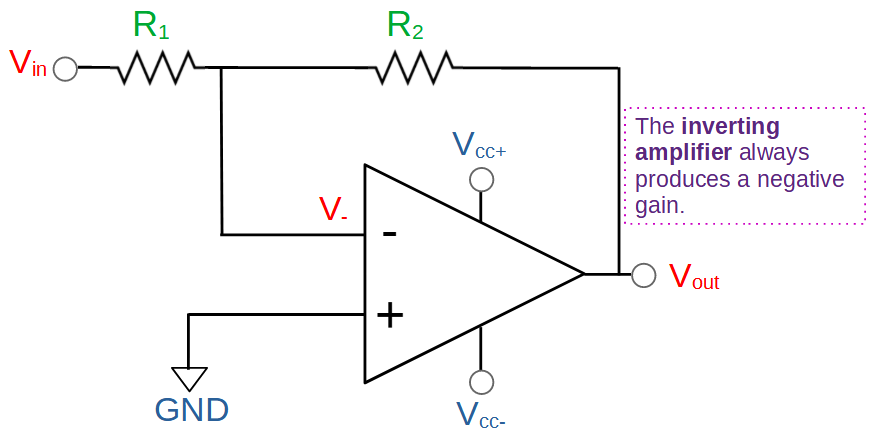
The inverting op amp is an amplifier that produces a gain with the opposite phase as the input. It has a negative gain value that is determined by two resistors, R1 and R2:
Gain=A_v=-\frac{R_2}{R_1}The negative sign of the gain indicates that the amplifier inverts the input signal. In other words, the output is the opposite polarity of the input. If the input is positive, then the output of the inverting op amp will be negative. If the input is negative, then the output will be positive.
Internally, the inverting op amp circuit relies on the core functionality of the operational amplifier, or ‘op amp’. Op amps generally come in the form of an integrated circuit, or chip.
What differentiates the inverting op amp from other op amp circuits is the configuration of the inputs and negative feedback loop. It strongly resembles the non-inverting op amp with the input and ground configurations exchanged.
As with other op amp circuits, the functionality of the inverting op amp is determined by how the op amp is used in the circuit. This includes the input configuration, feedback loop, and resistor values.
In this article we will cover the essentials of the inverting op amp. We will analyze the inverting op amp circuit and derive the formulas for gain and output. We’ll also look at a saturated inverting op amp circuit and see how the gain, output, and inverting input values differ from the ideal due to saturation.
What is An Inverting Op Amp?
An inverting op amp is a type of amplifier that uses an op amp to invert the input the signal. In other words, the output signal is 180° out of phase with the input signal. This means that the polarity of the output will always be opposite that of the input. This is represented by the negative sign in the gain formula, which we will derive below.
The inverting op amp is a quintessential example of an op amp circuit. Op amps can be used in many configurations in order to create circuits with different functionalities.
Like most op amp circuits, the inverting op amp uses a negative feedback loop that connects the output to the inverting input. In contrast, a positive feedback loop would have the output connected to the non-inverting input.
The inverting op amp circuit is almost identical to the non-inverting op amp in terms of circuit construction. The primary difference is the reversal of the inputs to the circuit. However, the inverting op amp is capable of reducing the magnitude of the output voltage as well as increasing it. This means that the non-inverting op amp can be used to step down the voltage within the range allowed by the supply rails.
Inverting Op Amp Circuit
The inverting op amp circuit is very similar to the non-inverting op amp. It features an op amp and two resistors (R1 an R2) in series, with the inverting input (V–) of the op amp connected between them.
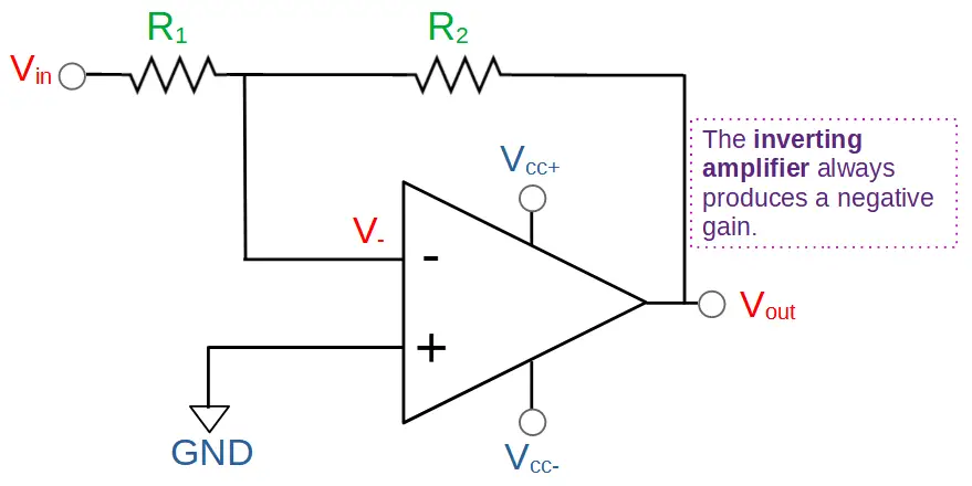
The output (Vout) of the op amp is connected to R2, forming a negative feedback loop.
The inverting op amp circuit relies on the basic functionality of the operational amplifier. The op amp has two inputs; an inverting input V– and a non-inverting input V+. It also has one output Vout:
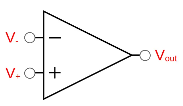
The primary function of the op amp is that it tries to equalize its’ inputs by adjusting its’ output. The output of the op amp Vout is stable when the two inputs are equal (V– = V+).
Op amps are constructed to enable negative feedback. If V+ > V– then the op amp will increase the output until the inputs are equal. If V+ < V– then the op amp will decrease the output until the inputs are equal.
In the inverting op amp circuit, the non-inverting input is connected to ground:
V_+=0V
As a result, the op amp will try to bring the non-inverting input to 0 volts. The op amp will adjust the output until the inverting input is equal to the non-inverting input:
V_-=V_+=0V
In order for this to happen, the op amp has to modulate its’ output. This action results in negative amplification of the input signal:
V_{out}=-V_{in}\frac{R_2}{R_1}Which is the desired output of the ideal inverting op amp. The gain is defined as the ratio of Vout to Vin:
Gain=A_v=\frac{V_{out}}{V_{in}}=-\frac{R_2}{R_1}We will derive the gain and output of the inverting op amp in the next sections.
Inverting Op Amp Gain
Let’s analyze the circuit in order to derive the gain formula for the inverting op amp:
A_v=-\frac{R_2}{R_1}Deriving this formula is very simple. We can start by observing that the non-inverting input of the op amp V+ is connected to ground and is therefore equal to 0V:
V_+=0 V
If the op amp is stable and not saturated, then the inverting input V– will also be equal to zero (0).
V_-=V_+=0V
This means that the input voltage Vin must be fully ‘dropped’ across resistor R1. We can use Ohm’s Law to write this as follows:
V_{in}=IR_1The output voltage Vout must be fully ‘dropped’ across resistor R2.
V_{out}=-IR_2The voltage drop is the opposite sign (relative to ground) as the drop across R1, which is signified by using a negative sign.
We can now calculate the gain using the ratio of Vout to Vin:
A_v=\frac{V_{out}}{V_{in}}=\frac{IR_2}{-IR_1}=-\frac{R_2}{R_1}There are a few interesting things to note about the gain of the inverting amplifier.
First, it’s negative. This means that the circuit will invert the input signal.
Second, it is a simple fraction. This means that it can take any value; the inverting op amp can be used to decrease voltage as well as increase it. This can be a useful feature because it allows the voltage to be decreased without having to attenuate it.
Note: In order to perform this derivation we had to assume that current does not flow into the inverting input, so that the current through R1 is the same as through R2. This allowed the ‘I’ term in the numerator and denominator to cancel each other out.
We also had to assume that the output is within the range of the power rails, i.e. the op amp is not saturated. We will see below that this formula doesn’t work if the output is saturated.
Inverting Op Amp Output
Now that we have found the gain of the inverting op amp, we can use it to calculate the output Vout.
By definition, the output is equal to the gain times the input:
V_{out}=V_{in}\times A_v=-V_{in}\frac{R_2}{R_1}Inverting Op Amp Example 1
Let’s look at an example of an inverting op amp circuit.
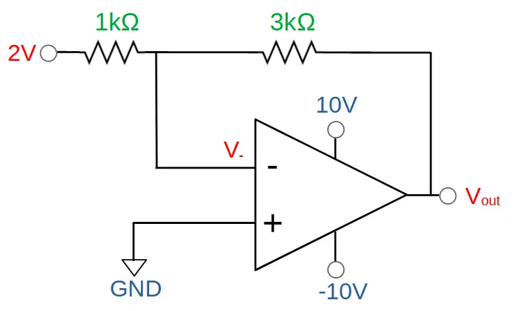
In this case we have set the input voltage to 2V. R1 is a 1kΩ resistor and R2 is a 3kΩ resistor.
Vin = 2V
R1 = 1kΩ
R2 = 3kΩ
For this circuit, find the gain Av and output voltage Vout.
Solution for Example 1
The gain can be determined by the formula:
A_v=-\frac{R_2}{R_1}=-\frac{3k\Omega}{1k\Omega}=-3The gain for this circuit is -3.
Given an input voltage of 2V, we can calculate the output voltage:
V_{out}=V_{in}\times A_v=(2V)(-3)=-6VThe output of this circuit will be -6V. Note that the power supply for this circuit is supplying -10V, so this circuit will be stable, i.e. it will not saturate.
Let’s see an example in which the op amp does saturate, and see how this changes the situation.
Saturated Inverting Op Amp
An op amp can only output voltages that are within range of the power supply rails. In other words, Vout is limited by Vcc+ and Vcc-:
Vcc- < Vout < Vcc+
If the output required to stabilize the circuit is within the range of the power supply, then the op amp will be able to make the inverting input equal to the non-inverting input. In this case, the circuit will be stable.
However if the required output is too high or too low for the op amp to achieve, Vout will instead saturate at the maximum or minimum voltage set by the power supply.
In the inverting op amp configuration, the inverting input will not be equal to 0V. The gain and output voltages will be different from the values predicted by the formulas.
Inverting Op Amp Example 2 – Saturated Inverting Op Amp
In this example, we will use the same circuit as in Example 1, but we will increase the input to 5V:
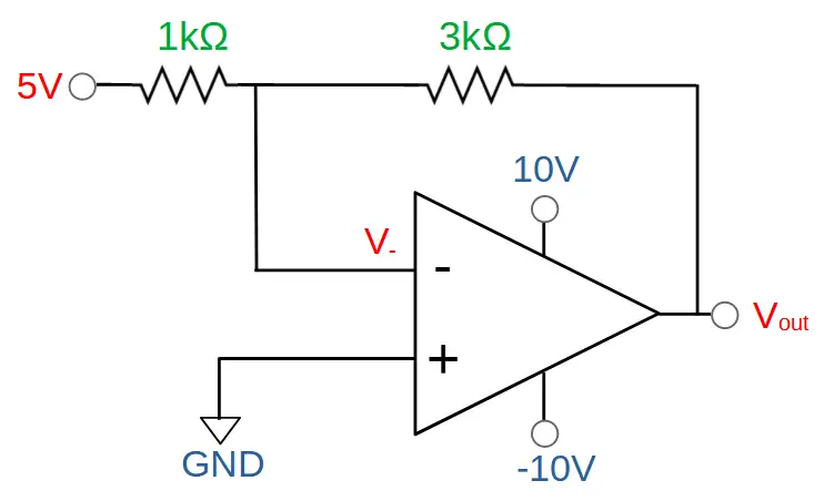
Vin = 5V
R1 = 1kΩ
R2 = 3kΩ
For this circuit, find the output voltage Vout, the gain Av, and the inverting input V–.
Solution for Example 2
Output of Saturated Inverting Op Amp
Let’s start by calculating the output voltage predicted by the formula:
V_{out}(predicted)=-V_{in}\frac{R_2}{R_1}=-5V\frac{(3k\Omega)}{(1k\Omega)}=-15VThe output voltage required to stabilize the circuit is therefore -15V.
But the power supply is only supplying -10V on Vcc-. This means that the op amp output will saturate before reaching -15V. The actual output can’t even reach -10V and will saturate at a slightly higher voltage that depends on the op amp itself. In this case, we can assume that it will saturate at around -9.5V:
Vout ~ -9.5V
To summarize: instead of Vout reaching the -15V required to stabilize the circuit, it instead saturates at around -9.5V.
Gain of Saturated Inverting Op Amp
We can use the output voltage Vout to calculate the gain Av:
A_v=\frac{V_{out}}{V_{in}}=\frac{-9.5V}{5V}=-1.9Instead of reaching a gain of -3 as predicted by the formula, this saturated circuit is only capable of reaching a gain of -1.9.
Inverting Input of Saturated Inverting Op Amp
In an ideal situation, the op amp would drive the output to -15V, resulting in 0V on the inverting input. The inverting input would equal the non-inverting input, which is connected to ground.
However in this case, the op amp output saturates at -9.5V. The output isn’t low enough to get the inverting input equal to zero because it is limited by the supply rails.
We can calculate the actual voltage V–.
The resistors R1 and R2 need to fully drop the total voltage difference between Vin and Vout.
V_{diff}=V_{in}-V_{out}=5V-(-9.5V)=14.5VWe can find the voltage dropped by R2 by taking the ratio of R2 to the total voltage dropped across R1 and R2:
V_{R_2}=V_{diff}\times\frac{R_2}{R_1+R_2}=14.5V\times\frac{3k\Omega}{1k\Omega+3k\Omega}=14.5V\times\frac{3}{4}=10.875VNote that this is just an example of a voltage divider.
The voltage on the inverting input V– is the difference between the output voltage Vout and the voltage dropped across resistor R2:
V_-=V_{R_2}-V_{out}=10.875V-9.5V=1.375VIn this case we can see that instead of being 0V, V– is actually 1.375 V due to the saturation of the op amp.
The Effects of Saturation on the Inverting Op Amp
We have seen that the output, gain, and inverting input values of the inverting op amp change dramatically if the op amp saturates.
These differences are noted in the table below:
| Vout | Av | V– | |
| Normal | -15 V | -3 | 0 V |
| Saturated | -9.5 V | -1.9 | 1.375 V |
How to Fix Inverting Op Amp Saturation
Saturation presents a significant issue because the circuit no longer functions as intended. The saturated circuit does not feature the predicted gain or output.
To solve this, we need to bring the predicted output within the range of the power supply. The easiest way to do this is to change the power supply rails so that they are greater than the range required for proper operation of the circuit.
In the above example, the op amp needs to be able to reach an output of -15V in order to prevent saturation. We can resolve this by ensuring that Vcc- is less than -15V. A good rule of thumb is that the power supply should be at least a few volts above or below the required level.
In this case, we can resolve this by supplying the op amp with around -20V:
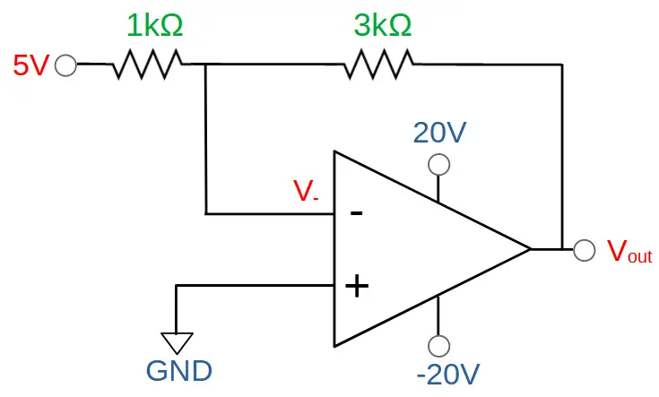
The op amp will be able to produce an output of Vout = -15V resulting in a stable circuit.
Using the Inverting Op Amp to Decrease Voltage
An interesting feature of the inverting op amp is that it can be used to decrease the voltage without attenuation. This is accomplished by choosing R1 to be a more powerful resistor than R2. If the value of R1 is greater than R2, the gain of the circuit will be less than one.
For example if want a gain of -.5, we can set R1 = 2kΩ and R2 = 1kΩ.
Using the gain formula:
A_v=-\frac{R_2}{R_1}=-\frac{1}{2}Of course this can also be achieved without using an amplifier at all. For instance you can simply use a voltage divider with two equal resistors. However op-amps have beneficial impedance characteristics that are not present using a voltage divider alone.
Inverting Op Amp Impedance
The impedance characteristics of the inverting op amp is very different from non-inverting op amp circuits. This is due to the fact that the input signal Vin is applied to the inverting input.
Non-inverting op amp circuits feature high input impedance and low output impedance. In a non-inverting op amp, the input signal Vin is applied to the non-inverting input. The input signal Vin ‘sees’ the internal resistance of the op amp, which is extremely high.
In contrast, in the inverting op amp Vin is connected to the inverting input. Instead of ‘seeing’ the internal impedance of the op amp, the input impedance is determined by the resistor R1. This means that to achieve high input impedance, we need to use a resistor R1 with a high value.
In order to achieve a high gain, R2 needs to be greater than R1. This means that constructing an inverting op amp circuit with high input impedance and high gain will require two high value resistors.
This is a critical factor because it determines suitable applications for the inverting op amp. When high input impedance is required, a non-inverting amplifier is required.
The inverting op amp shines in applications that require high noise tolerance, in particular common mode noise.
Inverting Op Amp Advantages
The advantages of inverting op amps include:
- Low cost
- Small size
- Resistant to noise
- High gain
- Capable of gain less than one
- Inverts signal while amplifying
Inverting Op Amp Disadvantages
- Input impedance is determined by R1
- Output impedance is low
- May not want inverted signal
Inverting Op Amp vs. Non-Inverting Op Amp
The inverting amplifier is a very similar circuit to the non-inverting amplifier in terms of construction.
Like the non-inverting amplifier, its gain is determined by the values of the two resistors. Both circuits look almost identical; the primary difference is that the input and ground configurations are reversed.
This configurational difference is what makes the two amps distinct, resulting in very different gain values.
Another difference is that the inverting op amp is capable of producing an output that is a fraction of the input. In other words, the output does not need to be greater than the output; the circuit can be used to reduce voltage without attenuation.
Finally, an important consideration when comparing the inverting op amp with the non-inverting op amp is the impedance characteristics. Non-inverting op amps have high input impedance, while inverting op amps have an impedance value that is determined by R1.
| Inverting Op Amp | Non-Inverting Op Amp | |
| Gain | -(R2/R1) | 1+(RF/R1) |
| Input Impedance | ~R1 | High |
| Output Impedance | Low | Low |
Inverting Op Amp – Conclusion
The inverting op amp is an essential example of an op amp circuit. It builds on other foundational op amp circuits like the buffer, comparator, and non-inverting op amp.
In this article, we have learned how to analyze the inverting op amp circuit. We’ve covered how the inverting op amp works, how to derive and calculate the output and gain, and some positive and negative aspects of the inverting op amp.
We have seen how saturation changes the output, gain, and inverting input V- and also compared the inverting op amp with the non-inverting op amp.
At this point, you should be comfortable with inverting op amp circuit fundamentals and analysis.