Pi Filter
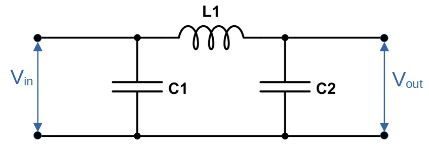
The pi filter is a type of passive inductor-capacitor (LC) filter that features its components in a ‘pi’ shaped configuration. It is called a ‘pi-filter’ because the shape of the circuit resembles the shape of the Greek letter pi (π).
Pi filters are commonly used as rectifier, low pass, and high pass filters. In each of these applications, a properly designed pi filter will dramatically improve the output quality of the signal.
Thanks to its combination of capacitors and inductors, the pi filter can achieve higher output quality than simpler filters like the L, C, or LC filters.
What is a Pi Filter?
A pi filter is a passive filter that uses a combination of capacitors and inductors.
When serving as a rectifier filter or low pass filter, the pi filter is made of two capacitors and one inductor. When the pi configuration is used as a high pass filter, the arrangement is reversed, featuring two inductors and one capacitor. Note that the rectifier filter is essentially just a low pass filter in which all AC components are ideally filtered out.
Pi filters are widely used because they do an excellent job of improving the output signal, improving both on simple L or C filters as well as on an LC filter with only one capacitor and one inductor.
Pi Filter Circuit Diagram
Pi Filter as Rectifier Filter
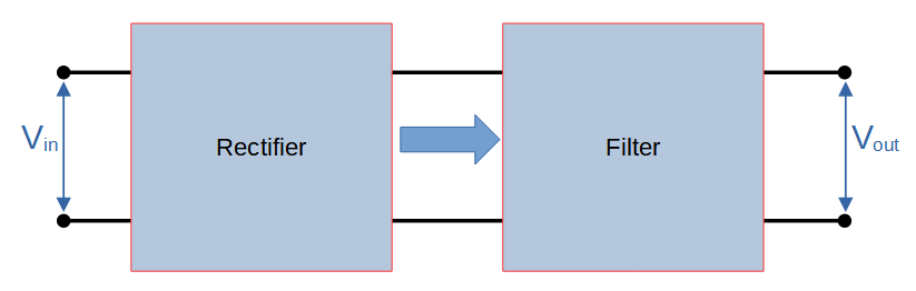
The first application we will cover is the pi filter as a rectifier filter. Rectifiers produce a pulsed output that has poor characteristics and needs to be filtered. In this case, the job of the pi filter is to flatten the output as much as possible.
An ideal rectifier (AC to DC converter) would output a signal with no (zero) AC component and 100% DC component:
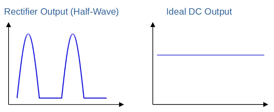
In comparison, real rectifiers produce a pulsed DC output that has relatively poor characteristics. This seems obvious because a pulsed signal does not bear much resemblance to a flat DC signal, but it is also reflected in properties like a high ripple factor. A high ripple factor indicates that the AC component within the rectifier output signal is large.
Pi filters are one of the most commonly used rectifier filters because they output a high quality signal but are relatively simple and inexpensive.
One of the most common configurations uses a bridge rectifier combined with a pi filter and voltage regulator to generate a DC voltage that is stable enough to use in electronic circuits. The components of these devices can be cheap, making this configuration exceptionally cost effective.
Pi Rectifier Filter Circuit
A pi filter circuit is constructed by using two capacitors and one inductor in a pi configuration.
In essence, it can be thought of as a multi-stage filter, with a capacitor filter stage followed by an inductor filter stage which is followed by another capacitor stage. Since an LC filter is comprised of a capacitor and inductor, the pi filter can also be thought of as a capacitor filter followed by an LC filter.
The primary difference between a single stage LC filter and a pi filter is the inclusion of a smoothing capacitor prior to the inductor stage. Instead of the inductor being supplied the pulsed DC output of the rectifier, in the pi filter it is supplied a waveform that is already smoothed by the first capacitor. This has the impact of maximizing the voltage and current output, and minimizing the ripple even before the inductor.
The result is an output with higher output and greater efficiency than an LC filter.
How Pi Filter Improves Signal Quality
The pi filter has three stages that each contribute to improving the signal quality:
The capacitor C1 functions as a smoothing capacitor in a capacitor-filter, smoothing out the pulsed DC waveform from the rectifier.
The inductor L1 allows the DC component of the waveform to pass and filters out AC components. In a typical inductor filter, the voltage waveform is centered around the average output. Because C1 keeps the output voltage close to the peak value of the pulses, it helps to increase the efficiency of the filter as a whole. The output of the inductor is greater than it would be without C1.
Capacitor C2 functions as a second smoothing capacitor, outputting a waveform that is of much higher quality. The result is a waveform with a satisfactory quality.
Pi Filter as Low Pass Filter
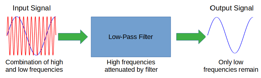
Another main application of the pi filter is as a low pass filter.
A low pass filter removes high frequencies from a signal, leaving only the frequencies below a cut-off frequency, fc.
A simple low pass filter can be made from just a single capacitor:
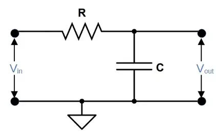
This circuit takes advantage of capacitive reactance, which is the impedance of the capacitor when supplied an AC signal. A capacitor allows high frequency signals to pass through it while blocking low frequency and DC components.
In the simple circuit shown above, high frequencies will short through the capacitor to ground. The capacitor will drop the low frequencies and DC components of the signal, and the output of our filter is taken across the capacitor. This means that we collect the low frequency and DC components and output them for the next stage of the circuit.
This simple, single stage filter can be improved by adding additional stages. A major improvement can be made by using an inductor in series with Vout and improved further still using the pi configuration, featuring two capacitors and an inductor:
Pi Filter Rectifier vs. Low Pass Filter
Note that when the pi filter is used as a rectifier filter, it is really just functioning as a type of low pass filter. The only distinctions are:
(1) the rectifier filter should ideally filter out all AC components rather than just frequencies above a cut-off fc.
(2) the filter is provided a pulsed DC input (i.e. typical rectifier input) rather than the mix of AC frequencies would would expect to see in a complex signal such as audio.
Pi Filter as High Pass Filter
The pi filter can also function as a high pass filter. To do so, the orientation of the capacitors and inductor is reversed. The circuit requires two inductors and one capacitor.
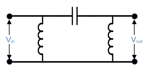
In this circuit, DC and low frequency signals are simultaneously blocked by the capacitor and shorted to ground through the inductors.
Higher frequencies will pass through the capacitor but will be impeded across the inductors. The output is taken from the second inductor after the high frequencies have passed the capacitor.
Pi Filter Advantages
Low ripple factor
Rectifiers would ideally produce a smooth DC signal, but they can’t do this without filtration. The amount of AC component that remains in the DC output of a rectifier is called the ripple factor. One job of a rectifier filter is therefore to minimize the ripple factor.
Pi filters are a simple and reliable way to significantly improve ripple factor from a rectifier circuit. The three stages of the pi filter combine to reduce the ripple and improve the output quality. The total ripple factor is improved when compared with an LC filter, and is dramatically improved compared to a single component filter.
Easy RF design
Pi filters are relatively easy to design in high frequency applications. They can often be integrated directly into the PCB traces using the capacitive and inductive properties of the traces themselves.
High output voltage
Pi filters are suited for power-related applications where high DC voltages are required.
Pi Filter Disadvantages
Pi Filters Can Be Expensive
Inductors can be expensive, particularly those with higher power ratings. This can lead to a relatively high cost for the pi filter in some applications.
Pi Filters Can Be Large
Both inductors and capacitors can be big and relatively heavy, so this can be a significant consideration depending on the application.