Wheatstone Bridge
A Wheatstone bridge is a circuit that uses three resistors and a voltmeter to measure an unknown quantity of electrical resistance.
The Wheatstone bridge is constructed by connecting two sets of two resistances in series/parallel bridge configuration. A voltmeter connects the two branches.
In the circuit above, Rx (the resistor on the lower right) is the unknown resistance that will be measured. R1 and R3 are resistors with known resistance values, and R2 is a potentiometer (an adjustable resistor). The circle in the middle labeled VG is a voltmeter; originally this would have been a galvanometer, hence the ‘G’ subscript.
While we would probably just use a multimeter to measure resistance today, the Wheatstone bridge continues to be used as a common example for further understand basic principles of analog resistive circuits.
Alternate Wheatstone Bridge Circuit Diagram
Although the Wheatstone bridge circuit is traditionally shown using the diamond configuration (which we use throughout this article), it is electrically identical to the series-parallel resistor circuit shown below:
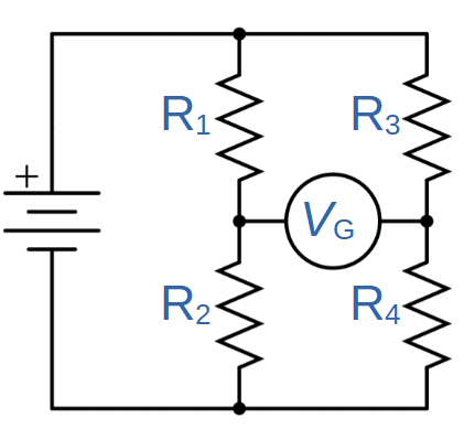
It’s a useful exercise to prove this to yourself and to understand why we can use different layouts to show the same circuit.
Balanced Wheatstone Bridge
A Wheatstone bridge circuit is known as either balanced or unbalanced depending on the values of the resistors.
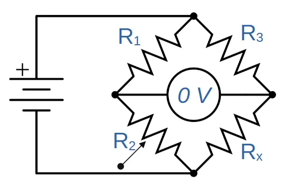
The first scenario is a properly balanced Wheatstone bridge circuit.
Balanced means that no current flows through the voltmeter in the middle; in other words, VG = 0.
This is shown in the figure below (note 0 V through the voltmeter):
In order for the circuit to be balanced, the points being measured must be at the same voltage. In other words, the voltage drop across R1 and R3 must be equal.
This condition is established by the ratios of resistance values. If the ratio between the resistors on the left (R1 and R2) and resistors on the right (R3, and Rx) are equal, then the circuit will be balanced and current won’t flow through the voltmeter:
\frac{R_1}{R_2}=\frac{R_3}{R_x}We can solve for Rx:
R_x=\frac{R_2R_3}{R_1}So if R1, R2, R3, and are all known, we can find the value of Rx.
How a Wheatstone Bridge Circuit Works
The Wheatstone bridge circuit uses the potentiometer (R2) and voltmeter (VG) together.
When the circuit is first constructed, chances are high that the circuit will be unbalanced. The voltmeter will measure a voltage difference between the right and left sides of the circuit (VG ≠ 0).
The potentiometer is then adjusted until the voltmeter measures zero volts, i.e. VG = 0.
Once the voltage measures zero and the circuit is balanced, the unknown resistance can be determined using the equation for Rx:
R_x=\frac{R_2R_3}{R_1}Different Wheatstone Bridge Configurations
The equations given above allow us to solve for an unknown resistance in all four of the possible locations.
If we change the value of Rx to R4, we can use the following diagram to solve for each of the different resistor locations in the Wheatstone bridge.
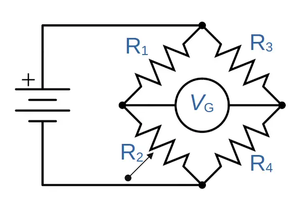
R_1=\frac{R_2R_3}{R_4}R_2=\frac{R_1R_4}{R_3}R_3=\frac{R_1R_4}{R_2}Wheatstone Bridge Problem No. 1
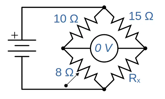
You have three resistors with known values connected in a circuit as shown.
Resistor R1 is 10 ohms, resistor R2 is 8 ohms, resistor R3 is 15 ohms and the unknown resistance is Rx. The voltmeter shows measures 0 volts indicating a balanced circuit.
What is the value of resistor Rx?
Using the Wheatstone bridge formula above:
R_x=\frac{R_2R_3}{R_1}=\frac{(8\Omega)(15\Omega)}{(10\Omega)}=\frac{120\Omega ^2}{10\Omega}=12 \OmegaUsing the classic Wheatstone bridge problem, we find that the value of Rx must be twelve ohms (12Ω).
Wheatstone Bridge Problem No. 2
What value of resistor R2 will balance the circuit shown below?
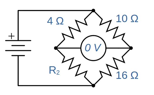
This time R2 is the unknown resistance. How can we find it?
Resistor R1 is 4 ohms, resistor R3 is 10 ohms and resistor R4 is 16 ohms. The voltmeter measures 0 volts, indicating a balanced circuit.
We can always use the ratios of the resistance values between the left and right sides to find any unknown resistance in a balanced circuit.
Since we’re solving for R2, let’s put that on top. Then, the ratio of R2 to R1 will be equal to the ratio of R4 to R3:
\frac{R_2}{R_1}=\frac{R_4}{R_3}We can solve for R2 by multiplying both sides by R1:
R_2=\frac{R_1R_4}{R_3}=\frac{(4\Omega)(16\Omega)}{10\Omega}=\frac{64\Omega^2}{10\Omega}=6.4\OmegaKirchhoff’s Laws for Wheatstone Bridge
A deeper analysis of the Wheatstone bridge can be performed by using Kirchoff’s current and voltage laws.
Kirchhoff’s Current Law for Wheatstone Bridge
Kirchhoff’s current law (KCL) states that the electric current flowing into a junction must equal the current flowing out of that junction.
Let’s see how this applies to the Wheatstone bridge.
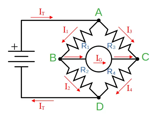
In the circuit above, we have labeled the four junctions of the circuit A, B, C, and D.
We have also labeled the current through R1 as I1, the current through R2 as I2, the current through R3 as I3, and the current through R4 as I4.
The total current flowing into and out of the battery is labeled IT, and the current through the voltmeter/galvanometer is labeled IG.
Since we have four junctions, we can set up four equations using KCL:
KCL for Junction A:
Current flowing into junction A = Current flowing out of junction A
(1) IT = I1 + I3
KCL for Junction B:
Current flowing into junction B = Current flowing out of junction B
(2) I1 = I2 + IG
KCL for Junction C:
Current flowing into junction C = Current flowing out of junction C
(3) I3 + IG = I4
KCL for Junction D:
Current flowing into junction D = Current flowing out of junction D
(4) I2 + I4 = IT
KCL with Balanced Wheatstone Bridge
When the Wheatstone bridge circuit is balanced, IG will equal zero (IG = 0).
In that case, we can rewrite equations (2) and (3):
(2b) I1 = I2 + IG => I1 = I2
(3b) I3 + IG = I4 => I3 = I4
We’ll use these results combined with Kirchhoff’s Voltage Law to derive the relationship between resistors in a balanced circuit.
Kirchhoff’s Voltage Law for Wheatstone Bridge
Kirchhoff’s voltage law (KVL) states that for any loop in the circuit, the total voltage must equal zero.
We can divide the circuit into two loops: ABC (or ABCA) and BCD (or BCDB). Let’s use KVL to form an equation for each loop.
Remember that the sign for each term is determined by the direction that we have assumed current will travel in (see the lesson on KVL for more information).
KVL for Loop # 1 (ABCA)
Voltage across R1 (V1) + Voltage across galvanometer (VG) – Voltage across R3 (V3) = 0
(5) V1 + VG – V3 = 0
Using Ohm’s Law (V = IR), we can restate this in terms of current and resistance:
(6) I1R1 + IGRG – I3R3 = 0
KVL for Loop # 2 (BCDB)
Voltage across galvanometer (VG) + Voltage across R4 (V4) – Voltage across R2 (V2) = 0
(7) VG + V4 – V2 = 0
(8) IGRG + I4R4 – I2R2 = 0
KVL With Balanced Wheatstone Bridge
Under balanced conditions, IG = 0 so that equations (6) and (8) can be rewritten:
(6b) I1R1 = I3R3
(8b) I4R4 = I2R2
If we multiply equation (8b) by equation (6b), we can solve for R4:
I_4R_4(I_1R_1)=I_2R_2(I_3R_3)
R_4=\frac{I_2R_2I_3R_3}{I_1R_1I_4}Now we can simplify using the results we found from KCL in a balanced circuit (I1 = I2) and (I3 = I4). We can use these relations to cancel out the two current terms in the numerator with the two in the denominator:
R_4=(\frac{I_2I_3}{I_1I_4})\frac{R_2R_3}{R_1}=(1)\frac{R_2R_3}{R_1}R_4=\frac{R_2R_3}{R_1}We have successfully used KCL and KVL to derive the relation between the resistances in a balanced Wheatstone bridge circuit.
Bridge Circuits
The Wheatstone bridge is the most popular example of a bridge circuit.
A bridge circuit is characterized by having two branches of electric circuit that are connected by a third branch that bridges them.
Variations of the Wheatstone bridge include the Wien bridge, Maxwell bridge, and Heaviside bridge.
A variation on the bridge circuit is also used in the bridge rectifier, where four diodes are used to change DC current into AC.
Like many bridge circuits, the Wheatstone bridge is a clever way of using basic electrical principles to achieve an interesting goal.