Voltage Divider

Key Points:
- Voltage dividers are passive circuits that output a fraction of the input voltage.
- They are used to generate reference points and new circuit branches with inputs at a particular voltage.
- Voltage dividers are really helpful for gaining intuition about circuits, because they can be used as a model to quickly calculate or estimate voltage in many situations.
- The rule/formula for the output voltage of a voltage divider is given by:
V_{out}=V_{in}\frac{R_2}{R_1+R_2}Why it’s important:
Voltage dividers are simple and common circuits that are used to generate a variety of voltages. They can produce voltage levels needed for other components or circuits. They are also used to provide points of measurement for reference or troubleshooting. Voltage dividers are a great real-world application that can help us to understand Ohm’s Law. The best thing about voltage dividers is that they can help you develop an intuitive understanding of the voltage at different points along a resistive branch of a circuit. You can model ALL of the resistors above AND below the points as being ONE resistor on either side. Then, with your intuition about voltage dividers, you can do a good job of estimating the voltage at any point along the branch.
Anatomy of a Voltage Divider
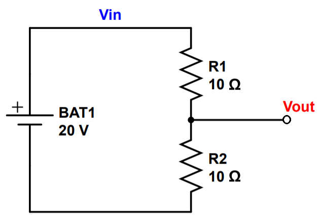
A voltage divider consists of resistors in series connected to a power source with at least one connection point between the resistors. The input voltage is designated Vin, and the output voltage is designated Vout.
There are two things that make voltage dividers powerful, and why they are so great to learn about early on in your electronics journey. 1) We can simplify any circuit or branch with resistors in series using a two resistor voltage divider as a model. Just sum all of the resistances above the measurement point and call it R1, and sum the resistances below and call it R2. 2) We can use an easy formula to calculate the output voltage knowing ONLY the input voltage and resistance values.
Let’s start with the classical approach, using Ohm’s Law.
Calculating Vout Using Ohm’s Law
There are three ways to calculate Vout. Two of them use Ohm’s Law, and the third (easiest) method uses the voltage divider rule.
Voltage Dividers Analysis Method # 1: The Painful Approach
In the example shown above, we have two 10 Ohm resistors in series, and a single connection point between them. This connection point provides a reference point or source voltage, known as Vout. Keep in mind that Vout does not necessarily need to have a wire or conductor leading to a test point. You’ll get the same result if the only connection is between R1 and R2, and you just measure the voltage at the output (negative terminal) of R1 or the input (positive terminal) of R2.
The voltage of Vout can be found using Ohm’s Law. Remember that the current depends on the total equivalent resistance of the circuit. First, we need to find the current in the circuit. The current is just equal to the battery voltage divided by the total resistance RT, which is the sum of R1 and R2.
I = \frac{V}{R_T} = \frac{V_{source}}{R_1+R_2}=\frac{20V}{10\Omega + 10\Omega} = 1ANow that we have the current through the circuit, we can find the voltage drop across R1, which we call V1.
V_1 = IR_1 = (1A)(10\Omega)=10V \\
V_2 = IR_2 = (1A)(10\Omega)=10V
Since Vout is directly connected to the output of R1, Vout is equal to Vin – V1:
V_{out}=V_{in}-V_1 = 20V-10V=10VWe can check our result by adding up the V1 and V2. The total voltage drop across both resistors should equal the source voltage of the battery, Vin– 20 volts.
V_T = V_1 + V_2 = 10V + 10V = 20V
We did it. In theory, you could use this simple method based on Ohm’s Law to calculate the voltage anywhere on a voltage divider.
Voltage Dividers Analysis Method # 2: Less Painful
If you’re paying careful attention, you might notice that Vout is actually equal to V2. So we could have skipped some of the calculations and calculated Vout more directly:
V_{out} = V_2 = IR_2 = (1A)(10\Omega) = 10VWhy the heck didn’t we just do that in the first place? Well, sometimes a voltage divider has a more complex circuit below Vout. In this case, the first method can be used so you don’t have to deal with calculating the resistance below Vout.
There’s a better way to calculate Vout if you know R1 and R2.
Deriving the formula requires you to understand method #1. One we have the formula, we can use it easily calculate Vout directly.
Why do we need better way to calculate the output voltage? It can be a little tedious to calculate the current and voltage drops across the resistors and then subtract from the input voltage.
So let’s learn about a simple formula that allows us to quickly calculate Vout using only Vin and the total resistance above and below the measurement point. This also called the voltage divider rule.
The Voltage Divider Rule
The formula to determine the output voltage if you know the total resistance above and below the position of Vout is:
V_{out}= V_{in}*\frac{R_2}{R_1+R_2}In this rule, ‘R1‘ represents the total resistance of the circuit above the point of connection for Vout, and ‘R2’ represents the total resistance below Vout.
It’s hard to emphasize how useful this rule really is. You can quickly get a sense of how a circuit is going to function if you have this rule in mind.
For instance, let’s look at three cases: one where R1 is much bigger than R2, another where R2 is much bigger than R1, and another where R1 is about equal to R2.
Voltage Dividers Case 1: R1 >> R2
In this case, R1 is much bigger than R2. What happens to Vout?
V_{out}= V_{in}*\frac{R_2}{R_1+R_2}Vout is equal to Vin times R2 over R1 plus R2. Vin stays the same.
Inside the fraction, the numerator (just R2) is small, but the denominator is really big because R1 is a high value.
With a small number over a really big number, we can approximate the fraction as being zero. Mathematically, this is like taking the limit of R1 approaching infinite. To any mathematicians in the audience: try not to have a heart attack.
If the fraction goes to zero, Vout also goes to zero. When R1 is much greater than R2, the voltage after R1 is almost zero.
How to interpret this result: Remember that the voltage is always the measurement of potential comparing one point to another. In this case we are comparing the voltage after R1 to ground, which we also assume is the voltage at the negative terminal of the battery. R1 is so big that we drop most of the voltage supplied by the battery. By the time we get to the output of R1, the voltage is close to zero.
Voltage Dividers Case 2: R1 << R2
In this case, R1 is much smaller than R2. Now what happens to Vout?
V_{out}= V_{in}*\frac{R_2}{R_1+R_2}Let’s look at the fraction again. R2 gets really big, making the numerator really big. However, R2 is also in the denominator making the bottom term really big too. In the limit that R2 goes to infinite, the fraction becomes R2/R2 which is equal to 1.
Vout becomes Vin times 1, which is just Vin.
When R2 is much bigger than R1, the output voltage Vout can be estimated as just the input voltage Vin.
Voltage Dividers Case 3: R1 = R2
In our final case study, let’s see what happens when R1 is about equal to R2. Let’s say you quickly scan a circuit and notice that R1 should about the same as R2, you can use this case to approximate what the output voltage will be.
Let’s look one more time at our voltage divider rule:
V_{out}= V_{in}*\frac{R_2}{R_1+R_2}This time, if R1 = R2, our fraction will become R1/2R1, which is equal to 1/2. So when the two resistance are close to equal, Vout will be approximately 1/2 Vin (Vin/2).
Developing Intuition Using Voltage Dividers
Why did we do all that (hand-wavy) math? It wasn’t to (hopefully not) confuse you. It was so that we can start to develop a deep intuition about resistors in series using voltage dividers. Here’s how I think about it:
- The closer R1 and R2 are to each other, the closer that that Vout will be to 1/2 Vin.
- The bigger R1 gets (compared to R2), the more Vout will approach zero (0). Vout gets closer to the voltage at the negative terminal of the source.
- The bigger R2 gets (compared to R1), the more Vout will approach Vin. Vout gets closer to the voltage at the positive terminal of the source.
The more you can integrate this kind of intuition into your mental circuit analysis pattern, the easier it will become.
Derivation of the Voltage Divider Rule
Let’s get back to basics and derive the voltage divider rule.
 \textrm{Note that that Vin is equal to the current times the sum of R1 and R2:} \\
(1): V_{in}=I(R_1+R_2) \\ ~\\
 \textrm{The voltage out is equal to Vin minus V1. We substitute Vin from the above equation:}\\
(2): V_{out} = V_{in}-V_1 = I(R_1+R_2)-IR_1=IR_2 \\ ~ \\
\textrm{We also rewrite the first equation in terms of I (current):} \\
(3): I = \frac{V_{in}}{R_T} = \frac{V_{in}}{R_1+R_2} \\ ~ \\
\textrm{We write equation (2) and then substitute I using eqution 3, solving for Vout.} \\
V_{out} = IR_2 = \frac{V_{in}}{R_1+R_2}R_2 = V_{in}\frac{R_2}{R_1+R_2}