Capacitors in Series
Why it’s important: Capacitors in series reduce the overall capacitance of the system. This can be used to engineer a specific capacitance using commonly manufactured components.
Review of Capacitance in Parallel
Capacitance is the ratio of the total charge stored in the capacitor to the voltage drop across it:
C = \frac{Q}{V}Where Q is the charge (in Coulomb), V is the Voltage, and C is the capacitance.
In parallel, capacitors act by increasing the total capacitance of the circuit. The total capacitance is the sum of the capacitors placed in parallel:
C_{Tparallel} = C_1 + C_2 + C_3 +...+C_NCapacitors in Series
When capacitors are placed in series, the total capacitance is reduced. Since current does not actually travel through capacitors, the total effect of capacitors in series is similar to separating the plates of the capacitor. Recall that the capacitance is proportional to the area of the plates, but inversely proportional to the distance between them:
C = \epsilon \frac{A}{d}When capacitors are connected in series, the capacitor plates that are closest to the voltage source terminals are charged directly. The capacitor plates in between are only charged by the outer plates.
In a series circuit, the total voltage drop equals the applied voltage, and the current through every element is the same. The charge on every capacitor plate is determined by the charge on the outermost plates and is limited by the total equivalent capacitance of the circuit.
In order to find the capacitance for capacitors in series, let’s start with the relation between capacitance, voltage and charge:
Q = CV
and rearrange this to solve for voltage:
V = \frac{Q}{C}Solving for voltages across individual capacitors, we find:
V_1 = \frac{Q}{C_1}, \hspace{2mm} V_2 = \frac{Q}{C_2}, \hspace{2mm} V_N = \frac{Q}{C_N}Noting that the charge must be the same across all capacitors because it is determined by the outermost capacitor plates.
The total voltage, VT, is the sum of the individual voltages and is equal to the voltage source when the capacitors are fully charged:
V_T = V_1 + V_2 + ...+ V_N = V_{source} \hspace{2mm} (when\hspace{1mm}fully\hspace{1mm}charged)Using the expressions for each value of voltage, we find:
V_T = V_1 + V_2 +...+V_N = \frac{Q}{C_1} + \frac{Q}{C_2} +...+\frac{Q}{C_N} = \frac{Q}{C_T}Where C_T is the total equivalent capacitance of the circuit.
If we take the last two expressions and divide by the charge (Q), we find:
\frac{1}{C_T} = \frac{1}{C_1}+\frac{1}{C_2}+...+\frac{1}{C_N}We can now solve for C_T by raising the whole equation to the -1 power:
C_T = (\frac{1}{C_1}+\frac{1}{C_2}+...+\frac{1}{C_N})^{-1}So when we think of capacitors in series, we can think of the overall effect as being similar to increasing the distance between the plates. The total capacitance decreases as more capacitors are added. Note that this is the same result we saw for resistors in series.
Let’s look at our first parallel circuit capacitor to understand more about the dynamics of the system.
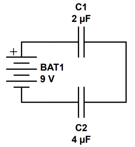
Example 1: Two Capacitors in Series
In this circuit, a 2 μF capacitor has been placed in parallel with a 4 μF capacitor.
a) What is the equivalent capacitance of this circuit?
C_T = (\frac{1}{C_1}+\frac{1}{C_2})^{-1}=(\frac{1}{2\mu F}+\frac{1}{4\mu F})^{-1} = (\frac{3}{4}\mu F)^{-1} = \frac{4}{3} \mu Fb) How much total charge will be stored in the capacitors of the circuit when fully charged?
Q = CV = (\frac{4}{3} \mu F)(9V) = 12\mu Cc) What is the voltage drop across each capacitor?
V_1 = \frac{Q}{C_1}=\frac{12\mu C}{2 \mu F}=6VV_2=\frac{Q}{C_2}=\frac{12\mu C}{4\mu F} = 3VNote that the total voltage is equal to the battery voltage:
V_T=V_1+V_2=6V+3V=9V
Example 2: Three Capacitors in Series
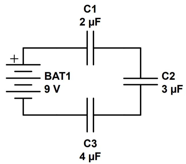
In this example, we have added a third capacitor in series between the capacitors from Example 1. Let’s see how this third capacitor changes the circuit.
a) What is the equivalent capacitance of this circuit?
C_T = (\frac{1}{C_1}+\frac{1}{C_2}+\frac{1}{C_3})^{-1}=(\frac{1}{2\mu F}+\frac{1}{3\mu F}+\frac{1}{4\mu F})^{-1}= (\frac{13}{12})^{-1}\mu F=\frac{12}{13}\mu Fb) How much total charge will be stored in the capacitors of this circuit when fully charged?
Q=CV=(\frac{12}{13}\mu F)(9V)=8.31\mu Cc) What is the voltage drop across each capacitor?
V_1=\frac{Q}{C_1}=\frac{8.31\mu C}{2\mu F}=4.15VV_2=\frac{Q}{C_2}=\frac{8.31\mu C}{3\mu F}=2.77VV_3=\frac{Q}{C_3}=\frac{8.31\mu C}{4\mu F}=2.08VAs a check, let’s ensure that the total voltage drop across the capacitors is equal to the total voltage supplied:
V_T = V_1+V_2+V_3=4.15V+2.77V+2.08V=9V
This confirms that we have calculated everything correctly.