Zener Diode Voltage Regulator
A Zener diode voltage regulator is a circuit that uses a Zener diode to maintain a constant DC output voltage.
An ideal regulator would output a constant voltage regardless of input fluctuations or variation of load current.
Zener Diode as Voltage Regulator
The Zener diode regulator uses a Zener diode to provide a consistent voltage output. Zener diode regulators are simple and cheap, making them great for many applications. The simplicity of a Zener diode regulator also makes it ideal for learning the concept of voltage regulators.
In order to understand how the Zener diode regulator works, we need to briefly review the Zener diode itself. This is because the functionality of the regulator relies on the special properties of the Zener diode.
Review of Zener Diodes
Zener diodes are a special type of semiconductor diode. Like other diodes, their primary component is a doped P-N junction. All diodes allow current to flow while they are forward biased. However, unlike other diodes, Zener diodes are also designed to allow current to flow when negatively, (or reverse) biased.
In other words, Zener diodes allow current to flow in both directions. But the current has different properties depending on the direction of current flow.
When the Zener diode is reverse biased, it features a a Zener voltage VZ. The Zener voltage VZ stays relatively constant even if the current fluctuates. Just as importantly, Zener diodes can be manufactured with different values of the Zener voltage VZ by changing the material properties of the PN junction. This means that it is easy to acquire Zener diodes with standardized Zener voltages, making them ideal in applications as a voltage reference or regulator.
This is shown in the current-voltage curve of the Zener diode.
As mentioned, the actual value of VZ depends on the semiconductor materials and construction of the diode. Hundreds of Zener diodes with different values of VZ are available. This means that when designing a Zener regulator, you can simply choose the Zener diode based on the required voltage output.
Zener Regulator Circuit
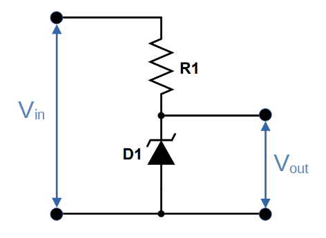
A Zener regulator is constructed by placing a Zener diode in series with a resistor, with the Zener diode having a reverse-biased configuration. This is similar to a voltage divider, with the second resistor being replaced by the Zener diode.
The voltage output is taken across the Zener diode, i.e. Vout = VZ:
Zener Regulator Circuit Diagram
This output is ordinarily connected across the load, as represented here by load resistor RL:
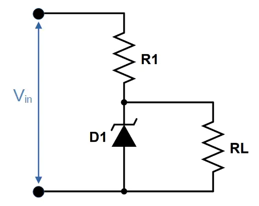
Unlike the resistor in a voltage divider, the Zener diode’s VZ will not change significantly with a change in current, so Vout should remain constant.
Zener Regulator Theory
Zener diode voltage regulators make use of the diode’s Zener voltage, which relies on the principle of quantum mechanical tunneling. In general, we can consider the voltage across the diode to be equal to the Zener voltage VZ. Since the load voltage is placed across the Zener diode, the load will also experience a total voltage of VZ.
The remaining voltage must be dropped across the resistor R1. In other words,
VR1 = Vin – VZ = Vin – Vout
Using Ohm’s Law, we can rewrite this as:
ITR1 = Vin – Vout
Where IT is the total current through the circuit and is equal to the current through the Zener diode plus the current through the load:
IT = IZ + IL
Note that all of the current must travel through R1, but the Zener diode and load will each only see some of the current. Since the load current also depends on the load resistance, we can see that load resistance can play a significant role in the dynamics of the circuit.
Zener Breakdown
Zener diode voltage regulators operate due to the principle of Zener Breakdown. When a P-N junction is made to be narrow, a sufficient voltage can cause electrons to tunnel through the depletion region, to the opposite side of the junction.
Tunneling
Tunneling is a quantum mechanical phenomenon that occurs because the electron has wave-particle duality. In quantum mechanics, electrons are modeled to be wave functions rather than simple ‘particles’. They are spread out in space, with a probability of being at a certain point. Due to this probabilistic nature, if a barrier (like the depletion region) is made small enough, there is a probability that the electron can tunnel through the barrier to the other side.
This is how Zener breakdown occurs; given enough energy by the electric potential difference across the Zener diode, the chances of an electron tunneling through the barrier increases dramatically.
Power Rating
The Zener diode has a maximum power rating that designates the maximum amount of electric power that it can safely dissipate.
Since a Zener diode has a relatively fixed Zener voltage VZ, the power rating essentially dictates the maximum current that the diode can handle:
Power \,Rating=V_ZI_{max}Therefore the maximum power
Designing a Zener Regulator
There are two components in a Zener diode voltage regulator: the Zener diode and resistor.
Therefore there are two primary choices that must be made when designing a Zener regulator. Generally, a diode is chosen first because its’ specs will determine the resistor needed.
The following steps will help in designing a Zener diode voltage regulator:
Choose a Zener Diode
The first design choice to make is choosing the Zener diode. Diodes come in a large selection of Zener voltages. The selection process starts by choosing a diode with a Zener voltage (VZ) that matches the output voltage that you want the regulator to provide.
You’ll also want to take power and current into account; different Zener diodes with the same VZ can be designed for different applications. The diode’s data sheet will often alert you to that diode’s intended uses as well as providing technical specifications.
There are two specifications you will need in order to choose a resistor:
(1) The diode’s breakdown current, also called the knee current or minimum current (Imin).
(2) The diode’s power rating, which is the maximum power at which it can safely be used. The power rating and Zener voltage VZ can be used to determine the maximum current:
I_{max}=\frac{P_{max}}{V_Z}Choose a Resistor
We just found two parameters for the Zener diode, Imin and Imax. We can use these parameters to determine the value of resistor needed to complete the circuit.
Determine the Minimum Resistance Value
The minimum value of resistance (Rmin) can be found by using the maximum current and plugging it into Ohm’s Law:
R_{min} = \frac{V_{in}-V_Z}{I_{max}}Note that Vin is the voltage supplied to the regulator.
Determine the Maximum Resistance Value
The maximum resistance value (Rmax) can be found by using the minimum current and plugging it into Ohm’s Law:
R_{max} = \frac{V_{in}-V_Z}{I_{min}}Determine the Ideal Resistance Value with Load Attached
Now that we know the minimum and maximum values of resistor that we need in order to safely use the chosen Zener diode, we can use the load resistance to find the ideal resistor.
We do this by applying Kirchoff’s Current Law (KCL), which states that the current leaving any junction must be equal to the current entering the junction. In this case, the current through the resistor (IR) must be equal to the current through the Zener diode plus the current through the load:
I_R=I_Z+I_L
We calculate the maximum and minimum load currents using both the minimum and maximum values for resistor R1 (note that the voltage across the load is equal to VZ):
Maximum load current:
I_{Lmax}=\frac{V_Z}{R_{min}}Minimum load current:
I_{Lmin}=\frac{V_Z}{R_{max}}Zener Regulator in the Power Supply
Zener regulators are commonly used in power supplies following the rectifier filter and bleed resistor.
The rectifier takes a sinusoidal AC signal and converts it into a pulsed DC signal.
The rectifier filter smooths the pulsed DC signal, producing a triangular/sawtooth waveform that has minimum ripple.
A bleed resistor dissipates any stored charge from the filter capacitors if the circuit is disconnected from the power source.
Finally, the Zener diode voltage regulator outputs a constant voltage, absorbing fluctuations in voltage and current.
Linear vs Non-Linear Regulators
Two broad classifications of voltage regulators are linear and non-linear.
Linear regulators use the transistor in the linear region, whereas non-linear regulators operate in cut-off or saturation modes.
Switched mode power supplies make use of non-linear regulators, and offer the advantage of greater efficiency and smaller size.
Discrete Component Regulators
Regulators that use discrete (i.e. individually packaged) components like resistors, diodes, capacitors, and inductors are known as discrete component regulators.
The Zener diode regulator is the most common linear, discrete component regulator and is an excellent introduction to the subject of voltage regulators.