Operational Amplifier
The operational amplifier is a DC voltage amplifier with high gain. Op amps are generally used in the form of an integrated circuit although they can also be constructed using transistors.
Several of the most popular integrated circuits of all time are op amps, including the 741 and 358 series op amps. Historically, op amps were one of the first examples of popular integrated circuits. For decades they have been widely produced, studied, and improved upon.
As a result, op amps can be obtained at extremely low cost, with high reliability, and they are widely used within the industry. They are versatile and considered foundational circuit elements of many electronics systems, useful to professionals and hobbyists alike.
What is An Operational Amplifier?
An operational amplifier is a type of voltage amplifier. They are extremely versatile circuits that are used to perform a wide variety of functions.
Op amps have their name because they can perform mathematical operations. They are capable of performing addition, subtraction, integration, and differentiation as well as many other functions.
An op amp is a voltage amplifier that is designed to use negative feedback.
Passive elements like resistors and capacitors are used to form complete circuits that include feedback loops to improve performance.
The feedback circuit, in large part, determines the operation (i.e. the ‘op’) of the op amp. By carefully designing the circuit, we can use the op-amp to do many different things.
The Problem With Transistor Amplifiers
In order to understand how op amps work, it’s a worthwhile exercise to review why op amps are so popular.
When amplifiers based on active components (i.e. transistors) were first produced, they had a few problems. They needed to be adjusted because gain tolerance was poor, and they also behaved erratically in the field. The gain tended to drift significantly, making early amplifiers difficult and costly to deal with.
This problem was solved by op amps, which use the concept of feedback to drastically improve an amplifier’s performance. From the very beginning, op amps have been associated with the first (intentional) feedback circuits; when you think ‘op amp’, you should also think ‘feedback’.
The underlying reason that op amps are more stable than transistor amplifiers, is that the total gain relies on a feedback circuit that consists of stable, reliable, predictable passive components rather than unstable, finicky active components (like the transistors in the amplifier itself).
How Op Amps Work
Structure of an op amp
Op amps can be considered three terminal devices, with two inputs and one output. These can be seen on the schematic symbol shown below:
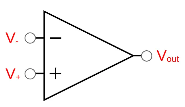
The three terminals are:
(1) Inverting input (V–)
(2) Non-inverting input (V+)
(3) Output (Vout)
The output of the op amp itself is the difference between the two inputs. Since the two inputs are being compared with each other to produce the output, they are collectively known as a differential input.
Like other amplifiers, op amps are characterized by their gain, A. In simple amplifiers, the open loop voltage gain AOL is the ratio of the output to the input voltage:
A_{OL}=\frac{V_{out}}{V_{in}} Note: The open loop gain AOL is sometimes written as AV or G. These are usually interchangeable.
At this point, you might notice that we have used a simple definition for the gain AV that uses one input and one output. But we’ve already seen that there are actually two inputs to the op amp, V+ and V–.
This is because op amps use a differential input, meaning that they use the difference between two inputs. In other words:
V_{in}=V_+-V_-So the open loop gain AOL is the output voltage divided by the differential input:
A_{OL}=\frac{V_{out}}{V_+-V_-}We can solve for the output of the circuit is equal to the gain times the differential:
V_{out}=A_{OL}(V_+-V_-)This means that the gain is equal to the ratio of the output to the difference between of the non inverting and inverting inputs:
A_{OL}=\frac{V_{out}}{V_+-V_-}In op amps, the voltage gain AV is also commonly known as the open loop differential gain, with the symbol AO. The gain of op amps is very large and is commonly of the order of 106 (100,000x).
Op Amps Need Power to Provide Gain
Op amps can’t break the laws of physics and create energy, so where does all that gain come from?
The extra energy must come from another source that acts as the main power source of the amplifier. We call the positive terminal VCC and the negative terminal -VCC.
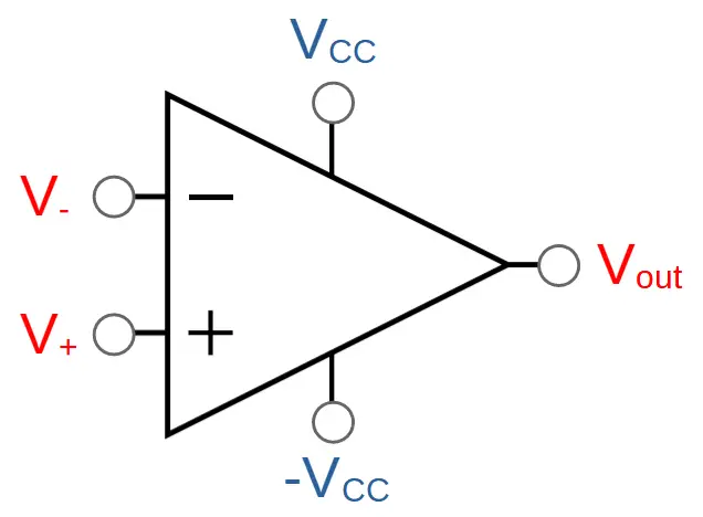
Sometimes VCC and -VCC will be included in a drawing for completion but in other cases they may be omitted for simplicity. Just keep in mind that amplification can’t take place without an external power source.
Ideal Op-Amps
The Golden Rules of Operational Amplifiers
There are a few qualities of ideal op amps that are useful to assume even though real life op amps aren’t ideal. These are also known as the ‘Golden Rules of Op Amps’.
- Infinite open loop gain. Open loop gain is the gain of the amplifier without any feedback (i.e. without a feedback circuit). Real op amps have high open loop gain (20,000-200,000) but we often just estimate that the gain is infinite unless designing a high precision circuit.
- Infinite input resistance. This means that current does not flow through the inputs of the op amp. In other words, I+ = I– = 0
- When the op amp is used with negative feedback, it will attempt to keep the difference between V+ and V_ equal to zero.
Behavior of Ideal Op-Amps
Ideal operational amplifier will behave reliably depending on the inputs V+ and V_.
It’s helpful to create a new term VΔ, which is equal to the difference between V+ and V_:
V_{\Delta}=V_+-V_-When VΔ is positive, Vout will tend to infinite:
for\: V_{\Delta}=V_+-V_->0:V_{out}\rightarrow \infinWhen VΔ is negative, Vout will tend to infinite:
for\: V_{\Delta}=V_+-V_-<0:V_{out}\rightarrow -\infinWhen VΔ is zero, Vout will also tend toward zero:
for\: V_{\Delta}=V_+-V_-=0:V_{out}\rightarrow 0Positive and Negative Feedback
An op amp can be used with positive or negative feedback, depending on which terminal is connected to the output.
Positive feedback is when the non-inverting input (V+) is connected with the output. This can be seen in the following circuit:
Negative feedback occurs when the inverting input (V_) is connected with the output.
Negative Feedback is Standard
When it comes to op amps, negative feedback is the standard. This configuration is known as an inverting operational amplifier.
Op Amps Are Integrated Circuits (ICs)
Internally, op amps are made up of components like transistors, resistors, and capacitors. They are complex enough that companies produce them in pre-packaged forms called integrated circuits.
Integrated circuits (ICs) contain the entire circuit inside of a single component.
The most popular op amp of all time, the 741, contains 20 transistors and 11 resistors. It can be purchased at very low cost, has a small footprint, and high reliability. It’s hard to beat the integrated circuit design.
Their popularity as integrated circuits is one of the reasons op amps are still so popular. The convenience of being able to design with them means that they will continue to be used in many applications.
Op-Amp Circuits
Op amps can be used in various ways to produce a wide variety of circuits. Each circuit has a unique gain and properties that make it useful in different situations.
Op-Amp Voltage Follower
The op-amp voltage follower is a unity-gain amplifier, meaning that it has a gain of 1. It is the simplest op-amp circuit with feedback and is therefore an excellent circuit to learn in order to understand op-amp functionality.
The op-amp voltage follower is created by connecting the output of the op-amp directly to the inverting input with a bare wire:
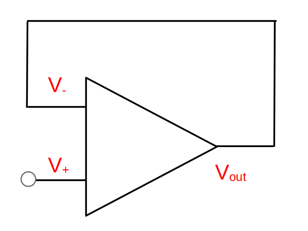
The op-amp voltage follower produces an output that is the same as the signal on the non-inverting input. In other words, it produces a gain of one:
Gain = A_v = \frac{V_{out}}{V_{in}}=1Although this may seem to be a trivial function, they are incredibly useful as buffer circuits.
This is because the op-amp itself has high input impedance and low output impedance. These helpful impedance properties allow the op-amp voltage follower to be used as a buffer between stages that would otherwise have a loss of signal strength. They are therefore also known as op-amp buffers.
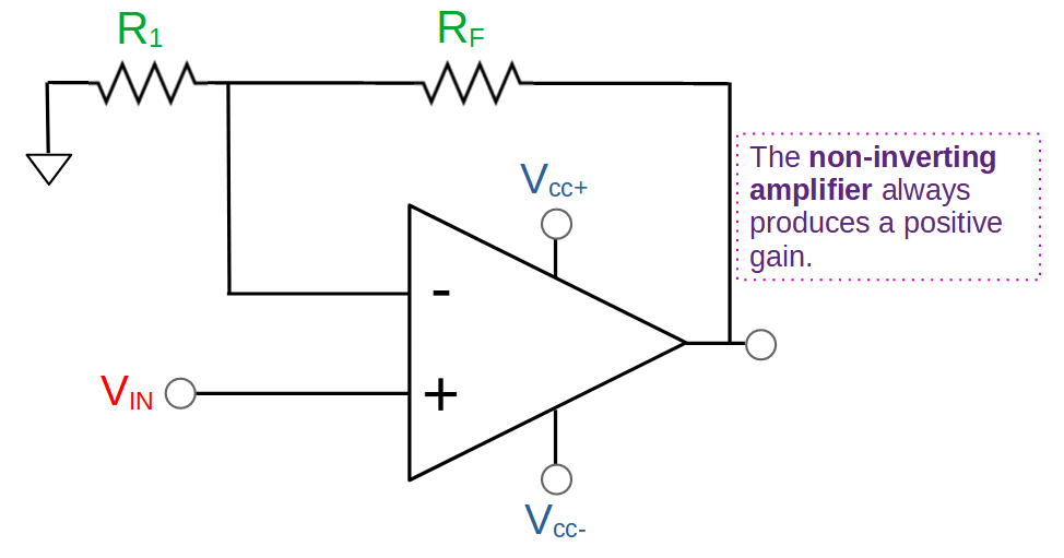
Non-Inverting Op Amp
A non-inverting op amp is a circuit that uses an op amp to produce a positive gain that is greater than one. The term ‘non-inverting’ in the name refers to the fact that in this configuration, the output is the same phase as the input.
We can see this reflected in its’ gain. The non-inverting op amp has positive gain, whereas an inverting amplifier has a negative gain because it inverts the signal.
Gain = A_v = \frac{V_{out}}{V_{in}}=1+\frac{R_F}{R_1}A non-inverting op amp uses two resistors (R1 and RF) that form a voltage divider between the op amp output and ground. The output of the voltage divider is fed into the inverting input to provide negative feedback to the circuit:
Inverting Op Amp
The inverting op amp reverses the polarity of the input signal as it amplifies. It is similar in construction to the non-inverting op amp. The primary difference in construction between the non-inverting op amp and inverting op amp circuits is the reversal of the input and ground connections.
An inverting op amp uses a negative feedback loop, with one resistor directly connecting the output to the inverting input, and another connecting the feedback node with the main input. These two resistors form a kind of voltage divider. However, the non-inverting input is grounded (V+ = 0); if the op amp is able to stabilize the circuit then V- will also equal zero (0).
The result of this configuration is that the polarity of the input signal is reversed; a positive input voltage results in a negative output (and vice versa). This is expressed by the negative sign in the gain formula for the inverting op amp:
Gain=A_v=-\frac{R_2}{R_1}