Alternating Current
Alternating Current (AC) is a type of electric current that alternates periodically over time. AC is the primary type of electrical current that is generated and used throughout the world. Whenever you plug something into a wall outlet, you are using AC power.
AC power is delivered to virtually every home and business in the world. Most home electronics also use AC power as an input, and those that require DC then convert AC power to DC. While having a deep understanding of AC isn’t a pre-requisite for learning electronics, learning just a bit can help you a great deal.
Alternating Current (AC)
Alternating Current (AC) is a type of electric current that alternates periodically in time. Let’s contrast this with direct current (DC). DC refers to a current that stays the same; its value never changes.
While DC sources provide a steady stream of electrons that never change direction, AC sources produce a current (and voltage) that changes with time. Electrons in an AC circuit first move one way through the circuit, and then move in the reverse direction. AC may seem complicated compared with DC, but AC power has some important advantages.
The primary advantage is that AC circuits can use transformers to increase or decrease voltage. Transformers rely on a changing current to function, so DC power won’t work. Even though DC power was developed before AC, AC quickly superseded DC due to the ability of the transformer to increase and decrease voltage. We’ll learn more about transformers later in this module.
The current and voltage produced by power plants represents a sine wave with a frequency and amplitude that is standardized within most countries in the world. In North America, the standard is 120 V, 60Hz power. In other words, the power grid in North America produces electricity that is 120 Volts (measured phase to ground) and that has alternates at a frequency of 60 times per second. Each time it alternates, the voltage ranges from positive (+) 120 Volts, all the way down to negative (-) 120 Volts, and back again.
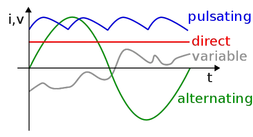
The plot below shows different types of currents. Direct current (DC) is shown in red, and alternating current (AC) is shown in green. Other types of current are also possible, but less common. A pulsating current has a periodic, steep rise and gradual descent toward a minimum voltage, and is shown in blue. A variable current is complex and/or random and is shown in grey. This module will focus on alternating current, which is represented by the green sine wave.
We use something called a waveform to describe the shape of a signal. A waveform is just a plot of the current and alternating current (AC) is called a sinusoidal waveform because its’ plot represents a sine wave.
Mathematically, an AC waveform is a sine wave that alternates between positive and negative values of the maximum voltage. The voltage oscillates at a certain frequency, which is the number of complete waves per second. At time t=0, the voltage is zero (0), and increases to a peak. It then decreases, passing through a voltage of zero (0), all the way down to a negative peak or valley. It then increases again to zero and continues this pattern. This is one complete cycle of the wave function.
This time-varying voltage can be described by the following equation:
v(t) = V_{max} sin (2 \pi f t) = V_{max} sin (\omega t)Where Vmax represents the peak voltage, t represents time (in seconds), and the relation between ω (the Greek letter omega) and frequency is given by:
\omega = 2pi f
Throughout the entire cycle, the current follows Ohm’s Law, and remains equal to the Voltage divided by the equivalent resistance of the circuit:
I = \frac{v(t)}{R_{eq}}= \frac{V_{max}}{R_{eq}}sin(\omega t)As you can see, both the voltage and current oscillate in time, following the pattern of a sine wave. At this point, you may still be a bit confused as to what this means.
How Can the Voltage or Current Be Negative?
The sine wave shape of an alternating current (AC) source indicates that electrons first move one way through a circuit, and then backtrack the other way. The steepness of the curve relates to how quickly the current is actually changing.
At the starting point (v=0, t=0) the electrons begin to move in the ‘positive’ direction. As the voltage increases, they move faster under increased voltage and current. When the voltage reaches the peak, the electrons are being pulled ‘harder’, under maximum potential. As the current declines from the peak, the electrons continue to be pulled in the forward direction until the voltage reaches zero. At this point, the electrons begin to be pulled in the other direction. They are pulled in the ‘negative’ direction with progressively more force until the voltage reaches the bottom of the valley. The electrons are then slowed under decreasing negative (i.e. increasing) voltage until the voltage reaches zero. The cycle then begins again as the electrons are once again pulled in the ‘positive’ direction.
Alternating Current Voltage Source Symbol
AC Voltage sources have a unique symbol to distinguish them from DC sources. The standard depiction of an AC source is that of a sine wave in a circle:
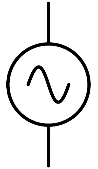
Other variations are common depending on the tool used to design the circuit layout. In general, the inclusion of a sine wave inside the symbol is the best indication that the source is AC.
AC vs. DC Circuits
AC circuits are just like DC circuits. They’re just…AC. In other words, you can turn a DC circuit into an AC circuit by changing the voltage source. This will effect the circuit in a number of ways. We’ll go over how AC circuits differ from DC circuits in the next section. The important thing to remember is that they really are just circuits, like DC circuits.
AC circuits allow us to use new components that won’t work in DC circuits. We can still use resistors and capacitors, but now we can also use transformers. Transformers are super important because they allow us to easily change the voltage (and current) in a circuit. Small transformers are useful in a variety of applications, but big transformers are right at the heart of the power grid.
In our lesson on power generation, we discussed that the primary reason AC current is chosen over DC is that the transformer allows us to change voltage easily. This has a significant impact on reducing losses in power transmission. Low voltage systems suffer huge losses when transmitted long distance, so the ability to increase the voltage for transmission and then decrease it for distribution, is vitally important.
How are AC Circuits Different From DC Circuits?
As mentioned, an AC circuit is really just a circuit with an AC voltage source. Let’s take a brief look at the properties of an AC circuit to see how they are different from DC circuits.
Voltage: In a DC circuit, the voltage stays the same all the time. But in an AC circuit, the voltage oscillates in time, as described by a sine wave. Since the voltage changes, you might wonder how we can say that the voltage is, let’s say, 120 VAC. At one moment the voltage might be 80 volts, and at the other it could be -110! Instead of measuring the voltage at any second, with AC systems we use something called the nominal voltage. The nominal voltage is equal to the Root Mean Square (RMS) of the maximum voltage. RMS is the square root of the average value of the squared function. So when we say that the power grid supplies 120VAC, we are saying that the root mean square (RMS) of the voltage supplied by the power grid is 120V. The peak voltage is actually 169 volts. We’ll discuss RMS in greater detail later in this module.
Current: In a DC circuit, the current stays the same all the time- because the voltage does not change. In an AC circuit, the current oscillates in time, with the same period and frequency of the voltage. The directionality changes, which means the sign (+/-) changes. As in DC circuits, electron flow is opposite that of current. However just as in a DC circuit, the current is described by the applied voltage divided by the resistance (this is just Ohm’s Law).
Resistance: Recall that resistors are just poor conductors that reduce or oppose current. They work the same whether or not the circuit is DC or AC. In DC circuits, resistors are the only components that reduce current flow in a circuit. However in AC circuits, resistors are no longer the only components that reduce current. In AC circuits, capacitors and inductors can also reduce current. The total sum of the resistance produced by all components (not just resistors) is called impedance.