Filter Circuits
A filter is a type of circuit that is used to improve the quality of an electric signal.
Two of the most common types of filters are AC filters and rectifier filters. AC filters are capable of passing (or amplifying) certain frequencies while attenuating (reducing) other frequencies. Rectifier filters are used to improve the DC output of a rectifier circuit, and can be seen as an extreme example of a low pass filter.
Thus, filters can extract important frequencies from complex signals that contain a combination of wanted and unwanted frequencies.
Filters can have a single stage or multiple stages. In general, adding stages increases cost and complexity but allows a higher quality output.
Filters are commonly used in radio communications, where they are used to attenuate all frequencies that are not part of the radio signals. Radio communications often use band-pass filters to achieve this.
Another common use for filter circuits is in audio processing, where they are used to attenuate frequencies that we do not want amplified such as low frequency vibrations.
The goal of this article is to introduce the basics of filters and how they work so that you can better understand them. We will start with explaining what a filter is, then move on to discussing some different types of filters including low-pass, band-pass, high-pass and all-pass filters as well as their uses in circuits.
Types of Filters
Low Pass Filter
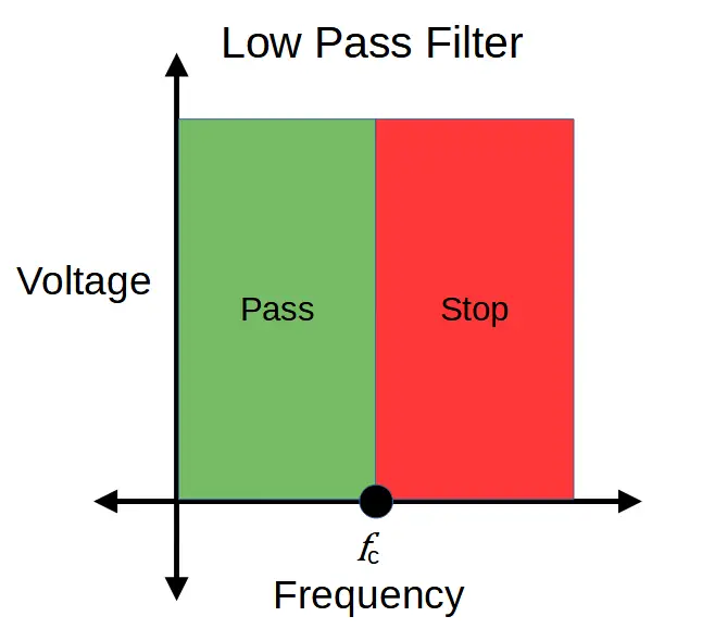
A low pass filter is designed to remove high frequencies from a complex input signal, leaving frequencies below the cut-off frequency of the filter fc.
High Pass Filter
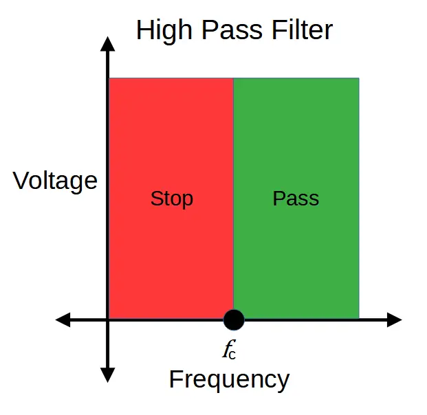
High pass filters remove high low from the input signal, leaving frequencies above the cut-off frequency of the filter.
Band Pass Filter
A band pass filter is designed to remove frequencies above and below a selected band called the passband. They can be thought of as a combination of a high and low pass filter that allows only select mid-range frequencies to pass.
Band pass filters have two characteristic frequencies; fL represents the low frequency cut-off and fH is the high frequency cut-off. The passband is between fL and fH.
Band Stop Filter
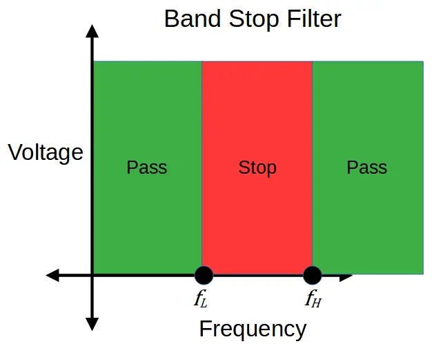
Band stop filters are the opposite of band pass filters. They filter out frequencies in a selected band and pass the frequencies that are higher and lower than the band.
Like band pass filters, band stop filters have two characteristic frequencies fL and fH. In this case the band in between fL and fH is called the stop band.
Notch Filter
A notch filter is a band-stop filter with a very narrow stop-band called a notch.
Passive and Active Filters
Filters are frequently designed with amplifiers to increase the strength of the output. A filter with an amplifier is known as an active filter, in contrast with passive filters, which don’t contain amplifiers.
Amplifiers are often necessary because while filters preferentially attenuate specific signals based on their design, there is no such thing as an ‘ideal’ filter. Real-life filters often attenuate desirable frequencies to a small degree, and an amplifier can be useful in improving the overall output of the filter.