Resistors in Parallel
A resistor is a passive, two terminal component that contributes a specific amount of electrical resistance to a circuit. They are used in virtually every circuit in the world, and in different configurations. ‘Resistors in parallel‘ refers to a configuration when the current can travel simultaneously through more than one resistor-containing path. This is also commonly called a parallel resistor configuration.
Resistors can be connected in series, in parallel, or in combinations of series and parallel.
When resistors are in parallel, they decrease the total equivalent resistance to below the value of the lowest value resistor.
Most circuits are complex, having both series and parallel sections. A parallel configuration means that electric current is offered more than one path through the circuit. These paths are usually referred to as branches.
The amount of current that travels through each branch is determined by the resistance of each branch. A branch with higher resistance will have less current flowing through it than a branch with lower resistance.
At the same time, more branches generally means more overall current flow. When new branches are added to the circuit, the total equivalent resistance of the parallel circuit decreases, even if every branch has the same resistance. This leads to an increase of the total current through the system.
If we use the analogy of water flowing through a pipe, if we were to add a second pipe, the resistance to water flow would decrease and more water would flow through the system due to the second pipe.
It turns out that electric current flows through conductors in much the same way as water through pipes. More parallel branches decrease the total resistance of the system, and thereby increase the current through the whole system.
The formula for the equivalent resistance for resistors in parallel is:
R_{eq} = \frac{1}{\frac{1}{R_1}+\frac{1}{R_2}+\frac{1}{R_3}+...+\frac{1}{R_N}}=(\frac{1}{R_1}+\frac{1}{R_2}+\frac{1}{R_3}+...+\frac{1}{R_N})^{-1}In our last lesson, we covered resistors in series. By exploring resistors in parallel, we are able to analyze the effect of resistive components in more complex circuits.
Review of Resistors in Series
It may seem like a small change, but resistors in series have a very different equivalent resistance than the same resistors in parallel.
In a series circuit, the total resistance simply adds:
R_{TSeries} = R_1 + R_2 + R_3 +...+ R_NR1 represents the resistance of resistor R1; R2 represents the resistance of resistor R2, and so forth. The total equivalent resistance of the series circuit is designated by RTseries, which is equal to the sum of the values of all resistors in series.
The total current in a series circuit depends on RTseries, and is given by Ohm’s Law:
I = \frac{V}{R_{TSeries}}Resistors in Parallel
Voltage
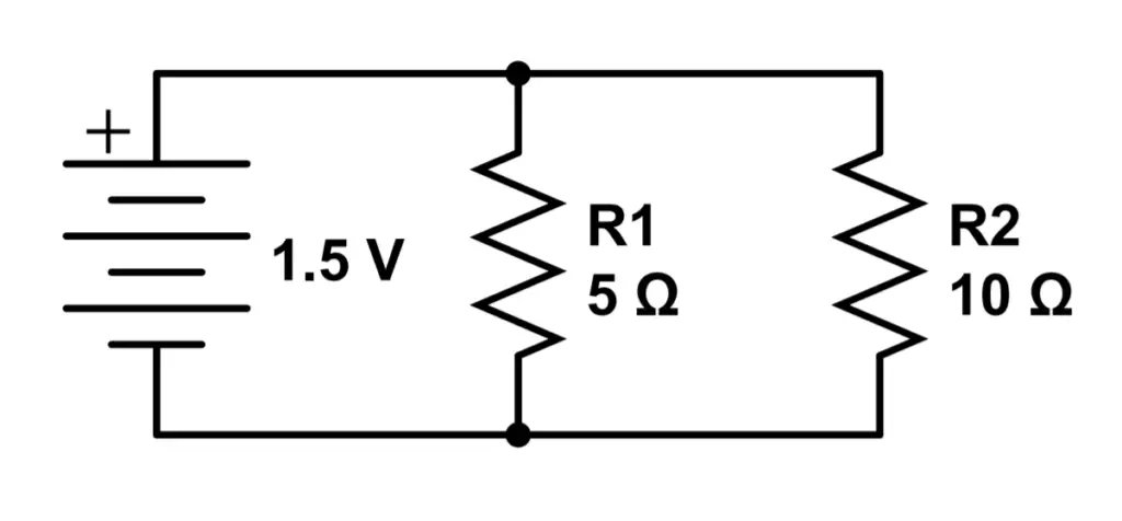
Let’s take a look at a circuit with two resistors in parallel. R1 and R2 are placed in parallel with each other. Our voltage source is a battery that provides 1.5 Volts. R1 and R2 are both connected directly to the battery’s terminals. If we measured the voltage across either resistor, we would find that both experience a voltage drop of 1.5 Volts. This makes sense because they are both connected directly to the battery’s terminals.
We can immediately see that both current paths have the same voltage.
Let’s clarify our discussion by looking closer at voltage in both series and parallel circuits. Just like in a series circuit, the voltage of the battery determines the total voltage across the circuit. In a series circuit, the voltage is the sum of each component’s voltage:
V_Tseries = V_1 + V_2 + V_3 + ...+V_N
In a parallel circuit, the voltage drop across every path is equal the total applied voltage. We can use this fact to calculate the total current, and current in each path.
V_Tparallel = V_1 = V_2 = V_3 = V_N
Current
What about current? In a series circuit, there was only one path for current to follow. Since the current is determined by the resistance of each path, a series circuit has only one value for current, and it’s the same for all components in that circuit.
I_{Tseries}= I_1=I_2= \frac{V_T}{R_T}In a parallel circuit, there are now multiple paths for current to follow. In the above schematic, current can flow from the positive terminal of the battery through R1 or R2. This time, the current has a choice. If the resistance of the paths are different, the current will be different for each path.
However, the total current through the whole circuit is still determined by the total resistance of the circuit. Just like with series circuits, we can combine the contributions of the resistors to find the total resistance of the circuit. We’ll call this the equivalent resistance, or Req. If we can find Req, we can use Ohm’s Law to find the current in the circuit. Let’s start by defining the total current IT as the sum of the currents from each of the two paths:
I_T = I_1 + I_2
Where I1 is the current through R1 and I2 is the current through R2. The total current through the circuit is simply the sum of the currents through each path.
In a parallel circuit, there are multiple paths for current to follow. Each path may have a different current, depending on the resistance of that path. The total current is the sum of the currents for each path.
We know from Ohm’s Law that the current through each path will be determined by the voltage and resistance through that path. We also know that the current through the whole circuit depends on Ohm’s Law using Req. as the equivalent voltage for the circuit. This time, the voltage across each path is the same:
I_1 =\frac{V_{source}}{R_1},I_2=\frac{V_{source}}{R_2}, I_T =\frac{V_{source}}{R_{eq}}Let’s use the to find the total equivalent resistance.
Resistance
Let’s combine the two results we found above:
I_T=I_1+I_2=\frac{V_{source}}{R_{eq}}=\frac{V_{source}}{R_1}+\frac{V_{source}}{R_2}Then divide by Vsource:
\frac{1}{R_{eq}} = \frac{1}{R_1}+\frac{1}{R_2}Taking the inverse, we find our result:
R_{eq}=\frac{1}{\frac{1}{R_1}+\frac{1}{R_2}} = (\frac{1}{R_1}+\frac{1}{R_2})^{-1}We can generalize this result for N (any number of) resistors:
R_{eq} = \frac{1}{\frac{1}{R_1}+\frac{1}{R_2}+\frac{1}{R_3}+...+\frac{1}{R_N}}=(\frac{1}{R_1}+\frac{1}{R_2}+\frac{1}{R_3}+...+\frac{1}{R_N})^{-1}In this case, we are assuming that each branch either has only one resistor, and we designate the total resistance of that branch with R1, R2, or R3. If a branch has more than one resistor, then the resistance of the branch adds just like in a series circuit. R1, R2, and R3 represent the total combined resistance of each branch.
We also find an interesting fact:
In parallel, the total resistance is often less than the resistance of each component. More parallel current paths decreases the total resistance.
Example 1 – Two Resistors in Parallel
Let’s answer the following questions for the above circuit:
1) What is the total resistance of the circuit?
To find the total resistance, we can use the formula using the reciprocal of the resistance.
R_T = \frac{1}{\frac{1}{R_1}+\frac{1}{R_2}} = \frac{1}{\frac{1}{5 \Omega}+\frac{1}{10 \Omega}} = 3.33 \OmegaAs a double check, we confirm that the total resistance is less than the resistance of either current path.
2) What is the current in each path and the whole circuit?
To find the current in the circuit, first we must find the current for each path and then sum the current in each path. Keep in mind that the voltage drop is the same across all parallel current paths.
I_1 = \frac{V_1}{R_1} = \frac{1.5V}{5\Omega}=.3AI_2 = \frac{V_2}{R_2} = \frac{1.5V}{10 \Omega} = .15AI_T = I_1 + I_2 = .3A + 1.5A = .45A
3) Calculate the power delivered to each resistor and the entire circuit.
P_1 = I_1^2R_1 = (.3A)^2(5\Omega) =.45W
P_2 = I_2^2R_2 = (.15A)^2(10\Omega) = .225W
P_T = P_1 + P_2 = .675W
We could also have calculated PT using the total resistance and voltage. This serves as a nice double-check.
P_T = \frac{V^2}{R} = \frac{(1.5V)^2}{3.33} = .675WExample 2: Three Resistors in Parallel
Let’s add a third resistor to our circuit. We will see that adding a third resistor will change our total resistance, total current, and total power dissipated. The voltage across each path is the same as the voltage of the battery.
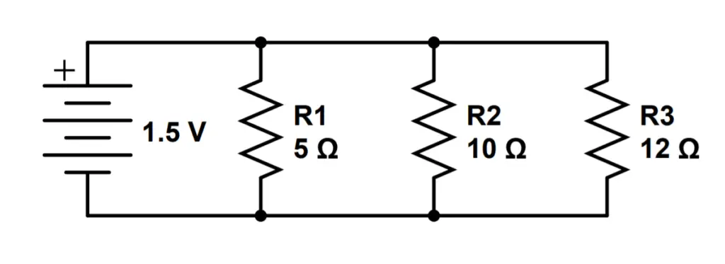
1) What is the total resistance of the circuit?
This time, we have three resistors to consider.
R_T = \frac{1}{\frac{1}{R_1}+\frac{1}{R_2} + \frac{1}{R_3}} = \frac{1}{\frac{1}{5 \Omega}+\frac{1}{10 \Omega}+\frac{1}{12\Omega}} = 2.61\Omega2) What is the current in each path, and in the whole circuit?
Just as in the first example, we can find the total current by summing the current from each path.
I_1 = \frac{V_1}{R_1} = \frac{1.5V}{5\Omega} = .3AI_2 = \frac{V_2}{R_2} = \frac{1.5V}{10\Omega} = .15AFor the first two resistors, the circuit is identical to that of the first example. Now that we have a third resistor, we must add the current from that path as well. The third resistor will change the total current in the circuit.
I_3 = \frac{V_3}{R_3} = \frac{1.5V}{12\Omega} = .125AThe total current is the sum of the current from each branch.
I_T = I_1 + I_2 + I_3 = .3A + .15A + .125A = .575A
3) Calculate the power delivered to each resistor and the entire circuit.
P_1 = I_1^2R_1 = (.3A)^2(5\Omega) =.45W
P_2 = I_2^2R_2 = (.15A)^2(10\Omega) = .225W
P_3 = I_3^2R_3 = (.125A)^2(12\Omega) = .1875W
P_T = P_1 + P_2 + P_3 = .45W + .225W + .1875W = .8625W
4) How has adding the third resistor changed the circuit?
Adding the third resistor decreased the overall resistance of the circuit, from 3.33 Ohms to 2.61 Ohms.
The total current increased from .45 Amps to .575 Amps.
The total power dissipated increased from .645 Watts to .8625 Watts.