Inductors in AC Circuits
Key Points:
- Inductors store energy in the form of a magnetic field; this mechanism results in an opposition to AC current known as inductive reactance (XL).
- Inductive reactance (XL) is a significant contributor to impedance because it causes the current to lag the voltage by 90°.
X_L = \omega L = 2\pi fL
Why it Matters:
Inductors are frequently used in AC circuits, most commonly as filters. Inductors contribute inductive reactance when used in an AC circuit. Inductive reactance is frequency dependent, and results in an opposition to current flow. Like capacitors but unlike resistors, inductors do not dissipate energy but rather, store and release it.
Capacitive vs. Inductive Reactance
The chart below presents a summary of key characteristics for capacitors and inductors in AC circuits. This lesson will discuss each of these characteristics for inductors in detail.
| Store Energy in a | Resulting in | Reactance Value | The current… | Current Equals | |
| Capacitors | Electric Field | Capacitive Reactance (XC) | XC = 1/(ωC) | Leads voltage by π/2 (90°) | IC = ωC Vmax sin(ωt + π/2) |
| Inductors | Magnetic Field | Inductive Reactance (XL) | XL = ωL | Lags voltage by π/2 (90°) | IL = (1/ωL) Vmax sin(ωt – π/2) |
Review of Impedance
We’ve seen that impedance is the total opposition to current flow in an AC circuit, and that it consists of both resistance and reactance:
Impedance = Resistance + Reactance
Reactance itself has two components, capacitive reactance (XC) and inductive reactance (XL). Reactance is also distinguished from resistance by multiplying it by ‘j’, the square root of negative one. Mathematically, impedance (Z) is represented by the following relation:
Z = R + j(X_C + X_L)
In the last lesson, we explored the topic of capacitive reactance in detail. This lesson will focus on inductive reactance.
Inductance in AC Circuits
An inductor consists of a coil wound around an insulator, and can be as simple as a coil of wire with nothing in the middle. Magnetic materials like iron can be used as a core to strengthen an inductor. Inductors store and release energy in a magnetic field, generating a back EMF as they produce a voltage that opposes a change in current. Inductors only opposes changes in current, not current itself (like resistance).
Inductors in AC circuits will continuously oppose the current through them, because the current is always changing. They still allow maximum current, but there is a delay caused by the storing and release of energy into and out of a magnetic field. When the voltage across the inductor is at its’ maximum point (Vmax), the current through the inductor is still increasing because of the delay in the inductor’s response. By the time the current has increased to its’ maximum point, the voltage has dropped to zero. This makes sense because when the current is at its’ peak, it is momentarily unchanging (slope of 0) so there should be no voltage drop across the inductor. By the time the voltage decreases to it’s lowest point (-Vmax), the current is at zero. So the current is always 90 degrees behind the voltage, resulting in inductive reactance (XL).
Just as with capacitive reactance, the current is no longer in phase with the voltage. As such, it opposes the current due to interference between the waveforms. Let’s analyze the circuit mathematically for more detail.
Current in an Inductive AC Circuit
Let’s look at an AC circuit consisting of an inductor and an AC source:
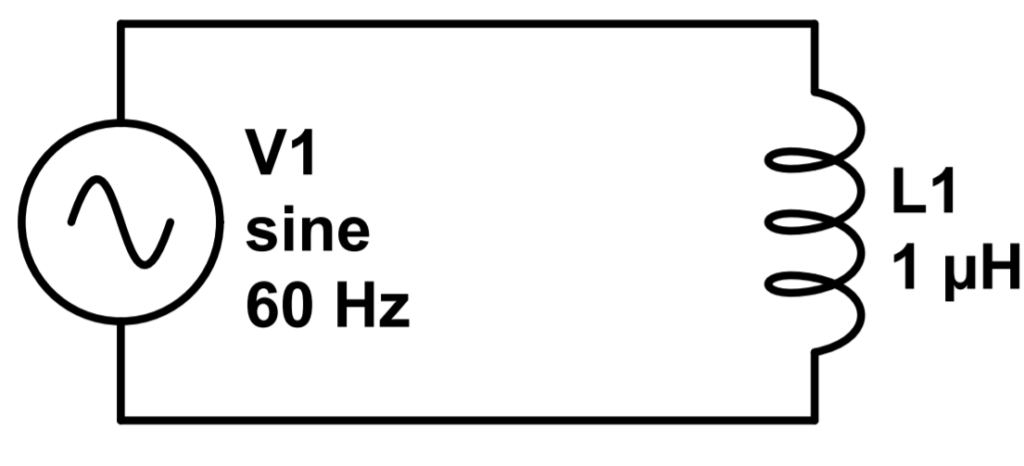
We can apply Kirchoff’s Voltage Law (KVL) to analyze this circuit. This entails adding the voltage contributions of each circuit element and setting them equal to zero. We follow the convention of calling a voltage ‘drop’ positive and a voltage source negative (the opposite approach will work as well). Our goal is to find the current in the circuit.
The contribution of the voltage source is a sinusoidal voltage of frequency f. We simplify the equation a bit by using a common abbreviation, ω = 2πf:
V_{source} = V_{max} sin(2\pi ft)=V_{max}sin(\omega t)The voltage across the inductor (VL) is the inductance value of the inductor (in henrys) times the time rate of change (d/dt) of the current in the inductor, IL. This relation is covered in our lesson on inductors.
V_{L} = L\frac{dI_L}{dt}Using our convention, the total voltage in the loop is the sum of these, with the source voltage set as a negative. According to KVL, this must equal zero:
-V_{source} + V_L = -V_{max}sin(\omega t) + L\frac{dI_L}{dt} = 0We can solve for dIL if we move the sine term to the other side, divide by the inductance (L), and multiply by dt:
dI_L = \frac{1}{L} V_{max}sin(\omega t) dtIntegrating each side, we find:
I_L = -\frac{1}{\omega L}V_{max}cos(\omega t)Which is a final result for the frequency dependent (ω = 2πf) current through an inductor in an AC circuit.
As with capacitors in AC circuits, it’s helpful to turn the cosine into a sine using the following trigonometric relation:
cos(\omega t) = -sin(\omega t - \frac{\pi}{2})So an equivalent way of writing the current through the inductor is as follows:
I_L= \frac{1}{\omega L}V_{max}sin(\omega t - \frac{\pi}{2})The current is now shifted by an additional term of pi/2. This is the mathematical description of the current lagging the voltage by 90 degrees, which we described above.
We can also use our finding to derive the capacitive impedance that we saw in the last lesson.
Derivation of Inductive Impedance
The current reaches its maximum value when the sine term is equal to one (1):
I_{max} = \frac{V_{max}}{\omega L}We now define inductive reactance (XC):
X_L = \omega L
So that the current is now the voltage over the inductive reactance (XL):
I_{max} = \frac{V_{max}}{X_L}Just as with capacitive reactance, this formula now resembles Ohm’s Law. Inductive reactance also now has units of ohms, so it’s compatible with resistance to compute impedance.