Low Pass vs. High Pass Filter
Filters are circuits that are used to remove part of an AC signal.
What is the difference between a low pass filter and high pass filter?
The difference between a low pass filter and a high pass filter is that a low pass filter will allow signals lower than a cut-off frequency to pass, while a high pass filter will allow signals higher than a cut-off frequency to pass.
The cut off frequency itself is determined by the components of the circuit.
It’s important to recognize that filters don’t create signals or change one frequency to another. For instance, a high-pass filter can’t create the high frequencies that they output. Instead, the input waveform contains a combination of high and low frequencies, and the high-pass filter prevents the low frequencies from passing through it.
Active filters contain amplifiers that take can boost the output of the filter circuit, which can make it seem like the filter is creating a signal that did not exist in the input waveform. However what’s happening in the filter circuit is simply that undesired frequencies are being filtered out, and the desired frequencies are then amplified.
The process of removing unwanted frequencies is called attenuation. A low pass filter primarily attenuates high frequencies, while a high pass filter primarily attenuated low frequencies.
Both low pass filters and high pass filters use a combination of a resistor and a capacitor. In an AC circuit, both resistors and capacitors contribute to the total impedance of the circuit.
Resistors contribute resistance, just like they do in DC circuits. Capacitors contribute capacitive reactance, which depends on the frequency of the input AC signal. The total impedance is the sum of the resistance and reactance.
Impedance = Resistance + Reactance
Low Pass Filter vs High Pass Filter Table
| High Pass Filter | Low Pass Filter | |
|---|---|---|
| Function | Passes frequencies above cut-off frequency. | Passes frequencies below the cut-off frequency. |
| Circuit Design | Capacitor in series with input, output measured across resistor. | Resistor in series with input, output measured across capacitor. |
| Usage | Useful in removing low frequency noise from signal. | Useful in removing aliasing effect. |
| Operating Frequency | Higher than the cut off frequency. | Lower than the cut off frequency. |
| Applications | Audio amplifiers, low noise amplifiers etc. | Communications circuit as anti-aliasing filter. |
Filter Cut-Off Frequency
Filters are designed with a specific frequency in mind which is called the cut-off, or corner, frequency.
Low pass filters are designed to pass frequencies below the cut-off frequency. A perfect low pass filter would pass all frequencies below the cut-off frequency, and none of the frequencies above the cut-off frequency.
High pass filters are designed to pass frequencies above the cut-off frequency. A perfect high pass filter would pass all frequencies above the cut-off frequency, and none of the frequencies below the cut-off frequency.
Since capacitive reactance depends on the signal frequency, filters can be designed so that the reactance dramatically increases either above or below the cut-off frequency. A low-pass filter will be designed so that the reactance increases above the cut-off frequency, with little to no reactance below the cut-off frequency
A high pass filter will be designed so that reactance increases below the cut-off frequency, with little to no reactance above the cut-off frequency.
Active vs. Passive Filters
Filters can be designed with either active or passive circuit components.
Passive filters utilize passive circuit components, like resistors, capacitors, and inductors.
Active filters utilize active circuit components, like operational amplifiers (op-amps). Active filters are capable of increasing the gain of the filtered signal.
Low Pass Filter
A low pass filter preferentially attenuates high frequencies, so that low frequencies are allowed to pass while high frequencies are blocked.
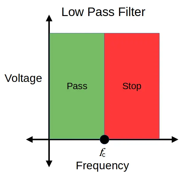
An ideal low pass filter would prevent any frequency component above the cut-off frequency from passing, but actual low pass filters aren’t perfect.
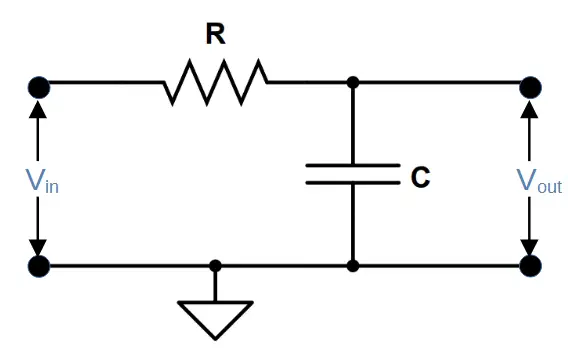
Both high and low pass filters use a combination of resistor and capacitor, but the arrangement is reversed in each. A low pass filter has the input signal applied directly to the resistor, and the output is measured across the capacitor:
Low Pass Filter Circuit Diagram
The characteristics of the low pass filter comes from the interplay of capacitive reactance and resistance, which both contribute to the total impedance.
The impedance contributed by the resistor (i.e. resistance) doesn’t depend on the frequency, but the capacitive reactance is inversely proportional to the frequency. This means that at low frequencies, the capacitive reactance is high while at high frequencies, the capacitive reactance is low.
X_C = \frac{1}{\omega C} = \frac{1}{2\pi fC}A simple way to think about low pass filters is with regards to the capacitive reactance and its effect on the voltage drop across the capacitor, which is the output voltage.
At high frequencies, the capacitive reactance is low. This means that the capacitor allows the signal to pass to ground without generating a significant voltage drop across it.
At low frequencies, however, the capacitive reactance is high, and the capacitor has a significant voltage drop across it. A higher voltage drop means a high output voltage for the circuit.
High Pass Filter
A high pass filter preferentially attenuates low frequencies, so that high frequencies are allowed to pass while low frequencies are blocked.
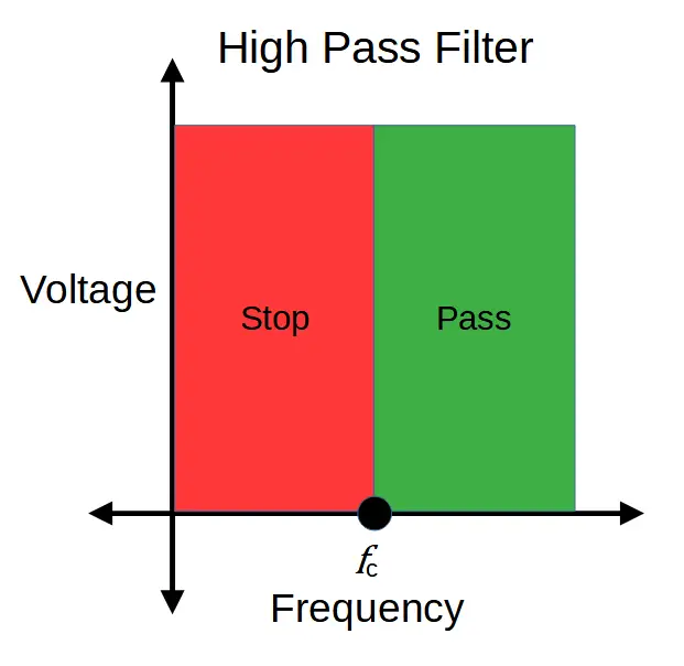
An ideal high pass filter would prevent any frequency component below the cut-off frequency from passing, but actual high pass filters aren’t perfect.
Both high and low pass filters use a combination of resistor and capacitor, but the arrangement is reversed in each. A high pass filter has the input signal applied directly to the capacitor, and the output is measured across the resistor:
High Pass Filter Circuit Diagram
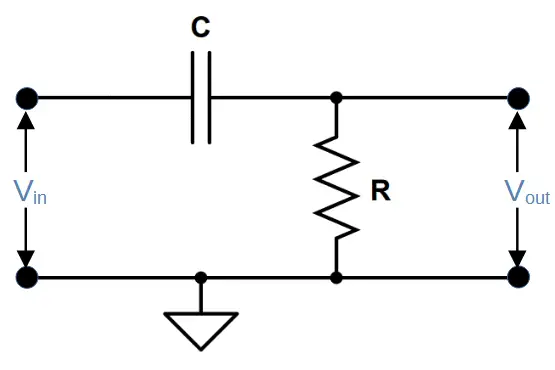
The characteristics of the high pass filter comes from the interplay of capacitive reactance and resistance, which both contribute to the total impedance.
The impedance contributed by the resistor (i.e. resistance) doesn’t depend on the frequency, but the capacitive reactance is inversely proportional to the frequency. This means that at low frequencies, the capacitive reactance is high while at high frequencies, the capacitive reactance is low.
X_C = \frac{1}{\omega C} = \frac{1}{2\pi fC}A simple way to think about high pass filters is with regards to the capacitive reactance and its effect on the voltage drop across the resistor.
At low frequencies, the capacitive reactance is high, and the capacitor has a significant voltage drop across it. The bulk of the voltage drop thus occurs across the capacitor, leaving little voltage to drop across the resistor.
At high frequencies, the capacitive reactance is low. The majority of the voltage must therefore be dropped by the resistor, leading to a high output voltage at high frequencies.
Summary
- The main difference between a low pass and high pass filter is that the low pass filter circuit passes frequencies lower than the cut off frequency while the high pass filter passes frequencies higher than the cut off frequency.
- Both low pass and high pass filters use a resistor and a capacitor, but the orientation in each is reversed. A low pass filter consists of a resistor followed by a capacitor, with the output voltage measured across the capacitor. A high pass filter consists of a capacitor followed by a resistor with the output voltage measured across the resistor.