Band Stop Filter
Filters are circuits that remove part of a complex AC signal.
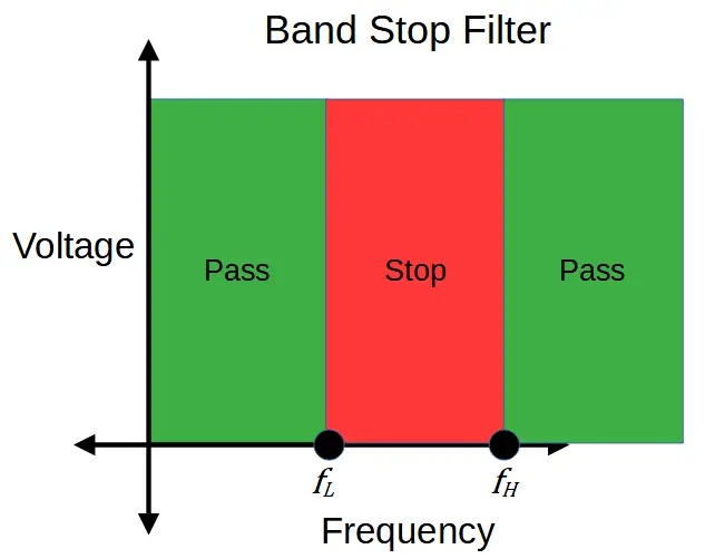
Band stop filters are filter circuits that remove a band of frequencies called a stopband, from an input signal. The band stop filter attenuates the frequencies within the stopband and outputs only the frequencies around it.
The process of removing unwanted frequencies is called attenuation. A band pass filter primarily attenuates high frequencies so that the resulting output is comprised of only frequencies within the passband.
Like other filters, band stop filters don’t create the frequencies they output; they simply attenuate the frequencies in the passband. If a frequency is not part of the input signal, the band stop filter will not produce it.
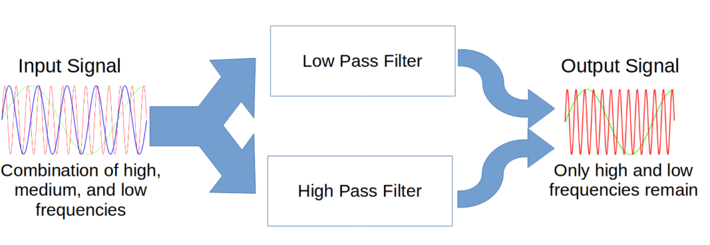
Like band pass filters, band stop filters are created by combining a high pass filter and a low pass filter. The key difference is that while the band-pass filters cascades the two filters in series, the band stop filter uses the two filters in parallel.
The passband is created by using a low pass filter that has a cut-off frequency fL at the bottom of the stopband, and a high pass filter with a cut-off frequency fH at the top of the stopband.
Band Stop Filter vs. Band Pass Filter
Band stop filters are similar to band pass filters in terms of construction and operation.
However, band stop filters perform the opposite action of band pass filters, which output a band of frequencies called a passband. In design, they are similar to band pass filters in that both types of filter utilize a combination of a low pass and a high pass filter.
The difference is that band stop filters use a low pass filter in parallel with a high pass filter. In contrast, band pass filters cascade a high pass filter in series with a low pass filter.
To remove a band of frequencies, the low pass filter is used to generate the low cut off frequency fL while the high pass filter is used to generate the high cut off frequency fH,. The frequencies between fL and fH are attenuated.
Band stop filters are also called band reject filters or band elimination filters. Notch filters are a type of band filter that are designed to attenuate a very small range of frequencies.
How Band Stop Filters Work
Band stop filters take in a complex input signal that consists of a variety of different frequencies.
The input signal then travels through two filters that are placed in parallel.
Each filter has a cut-off frequency that is determined by the parameters of the filter elements, i.e. the resistance and capacitance.
The two filters work in parallel, with each filter producing a different part of the final output signal.
A low-pass filter allows all of the frequencies below the cut-off frequency, fL, to pass. It establishes the low-frequency side of the band-stop filter.
The other is a high-pass filter, which allows all of the frequencies above fH to pass. It establishes the high-frequency side of the output.
The two frequencies are then combined to produce the final output of the band-stop filter.
Capacitive Reactance
Both filters rely on the concept of capacitive reactance in order to function.
Capacitive reactance (abbreviated XC) is a frequency dependent term, and determines the voltage drop across the capacitor.
The following equation expresses capacitive reactance as a function of both frequency (f) and capacitance (C):
X_C = \frac{1}{\omega C} = \frac{1}{2\pi fC}The capacitive reactance is inversely proportional to the frequency.
This means that a high frequency will result in a low capacitive reactance, and the signal will pass through the capacitor relatively unhindered. A low frequency will be effectively blocked, with a large voltage across the capacitor at low frequencies.

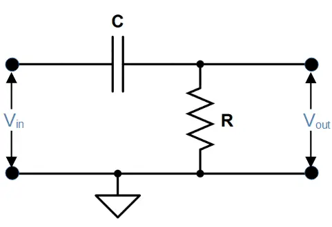
A high pass filter makes use of this phenomenon by taking its’ output through the capacitor, while a low pass filter takes its output across the capacitor. This simple configurational difference is what allows each filter to work.
The band-pass filter makes use of both in order to achieve an output of a selected frequency passband.
Band Stop Filter # 1: Low Pass Filter
The first filter in the band stop filter is the low pass filter.
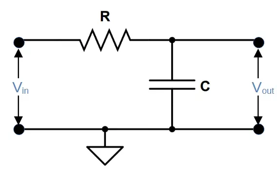
Low pass filters feature a resistor and capacitor in series. The output is taken across the capitor, which attenuates frequencies higher than the cut-off frequency fL. This allows the circuit a high output when the capacitive reactance (and the frequency) is high.
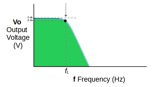
As a result, frequencies below the stopband are allowed to pass by using a low pass filter with a cut-off frequency of fL.
Above fL the output rapidly decreases. This creates the low-frequency portion of the band-stop filter output.
The cut-off frequency fL is determined by the values of resistor R1 and capacitor C1 in the circuit.
f_L = \frac{1}{2 \pi R_1 C_1}The output of the low-pass filter does not pass through the high-pass filter like the signal in a band-pass rectifier; instead, each filter produces a separate signal that is combined to produce the final output.
Band Stop Filter # 2: High Pass Filter
The second filter used to create the stopband is a high pass filter.
High pass filters also feature a capacitor and resistor in series. The capacitor produces a capacitive reactance that is low at high frequencies and high at low frequencies. Low frequencies in the signal are attenuated when they encounter the capacitor. The output is then taken across the resistor, allowing only the high frequencies to pass.
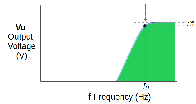
Frequencies below the passband are thereby attenuated by using a high pass filter with a cut-off frequency of fH.
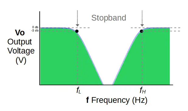
The cut-off frequency fH represents a voltage drop of -3db, or 70.7% of the input signal.
Below fH the signal strength declines rapidly.
The cut-off frequency fH is determined by the values of resistor R2 and capacitor C2 in the circuit.
f_H = \frac{1}{2 \pi R_2 C_2}Combining the High and Low Pass Filters
In order for the band pass filter to function, the two filters must operate in parallel together.
The input signal is split between the two filters, passes through both, and the outputs are combined.
The complete circuit therefore allows the high pass filter to attenuate frequencies below fH, and allows the low pass filter to attenuate frequencies above fL. When the two are combined, the full output featuring a stopband is produced.
Bandwidth
Like band pass filters, band stop filters introduce the concept of bandwidth, which is the size of the passband in hertz. Mathematically, bandwidth is defined as the difference between fH and fL:
Bandwidth = fH – fL
A filter with a wider bandwidth therefore attenuates more frequencies than a filter with a smaller bandwidth.
Band stop filters with an extremely small bandwidth are referred to as notch filters.
Ideal vs. Actual Band Stop Filters
In this tutorial, we have discussed ideal band stop filters. It’s important to recognize that real-life band pass filters have important limiting factors.
One significant issue, which we can see in the plots above, is that the stopband may not feature a steep enough cut-off for a given application. If the required stopband is narrow enough, the frequencies in the middle of the band may still be allowed to pass with a magnitude that is too high.
For this reason, in practice band stop filters often use several filter circuits combined with amplifiers to improve the overall quality of the output signal. It is also common to introduce inductors for the same reason. However the basic functionality remains the same as the filter circuit introduced in this article.