Operational Amplifier Voltage Follower (Op Amp Buffer)
The operational amplifier voltage follower, also called an op-amp buffer, is an op-amp circuit that uses a bare wire to provide feedback to the inverting input.
The op amp buffer is the simplest configuration for providing feedback to an operational amplifier. This is because it doesn’t use any components like resistors or capacitors outside of the op amp.
The op amp buffer achieves a gain of one. It does not actually amplify the input, but instead mirrors it. In other words, if the input is 10 volts, the output will also be 10 volts.
This might seem useless but the op amp buffer is actually an incredibly useful circuit! This is because it has excellent impedance properties. It exhibits high input impedance, meaning no/low current flows into the op amp. At the same time, it has low output impedance; meaning that it can drive other stages without issue.
Despite its’ simplicity, the op-amp buffer is an incredibly useful circuit.
What is an Operational Amplifier Voltage Follower?
The op amp voltage follower, also called an op-amp buffer, or unity-gain amplifier, is a simple op amp circuit. It uses a simple feedback configuration to produce a stable output voltage.
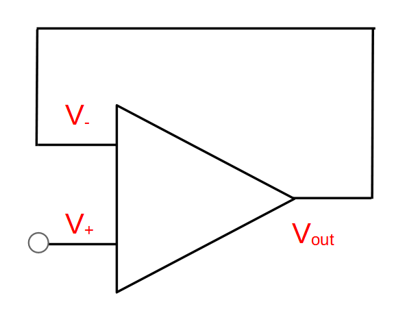
The op amp voltage follower is created by directly connecting the output of the op amp to the inverting (-) input.
How the Op Amp Voltage Follower Works
To understand how the op amp voltage follower/buffer works, we have to review the properties of operational amplifiers themselves.

- Op amps have two inputs, and they try to get both inputs to match. One input is called the non-inverting input, and is designated with a plus (+) sign. The other input is the inverting input, and is designated with a minus (-) sign.
- The op amp assumes that the output may be connected to the inverting input (-) in a feedback loop. It will try to drive the output so that the inverting input (-) matches the voltage it detects on the non-inverting input (+).
- If the voltage on the inverting input is lower than the voltage on the non-inverting input, the op amp will increase the output until either a) the two input voltages are equal or b) it can’t drive the output voltage any higher.
- If the voltage on the inverting input is higher than the voltage on the non-inverting input, the op amp will decrease the output until either a) the two inputs are equal or b) it can’t drive the output any lower.
The op amp voltage follower circuit takes advantage of these basic principles of op amp functionality by directly connecting the output with the inverting input:
The output will therefore dictate the inverting input; if the output is 5 volts then the inverting input will also be 5 volts.
Since the op amp wants to match the inputs, the output will equal whatever the non-inverting input is, and the inverting input will therefore also be equal to the non-inverting input.
Let’s look at a few examples to help better understand how op-amp voltage follower circuits work.
Example 1: Op-Amp Voltage Follower On Startup
A great way to understand the op-amp voltage follower is to look at what happens when the circuit is first turned on, or a voltage is first applied.
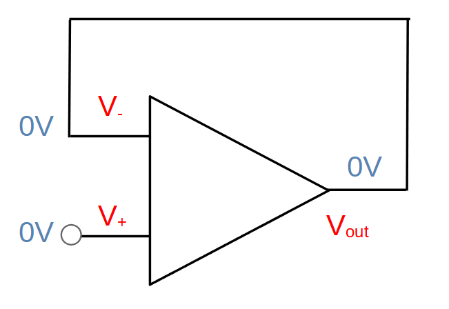
Initial condition: Before we apply any voltage to the op amp, the non-inverting input will be zero volts. The output will be zero volts and therefore the inverting input will also be at zero volts.
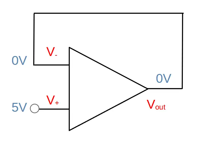
Startup: We apply a 5V signal to the non-inverting input. At this moment, the inverting input is still at 0V:
Now the op-amp gets to work!
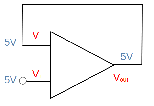
The op amp senses that the non-inverting input has a higher voltage than the inverting input, and drives the output up. The output increases until the op amp no longer senses a voltage difference between the inputs. In other words, the op amp will increase the output until the signal on the inverting input reaches 5V. To do so, the output must also equal 5V:
Mathematically, this sequence is described by the following equations:
V+ = Vout = V–
Voltage Gain = Av = 1
We can see that whatever the voltage is on the non-inverting input, will be produced on the output. The gain of the op-amp is one, which is why the circuit is also called a unity gain amplifier.
Example 2: Op-Amp Voltage Follower Input Voltage Increased
Now let’s look at what happens when the voltage on the non-inverting input is increased.
In this case, we will start with the the circuit in the same state as at the end of example number 1; 5V on the both inputs as well as the output:
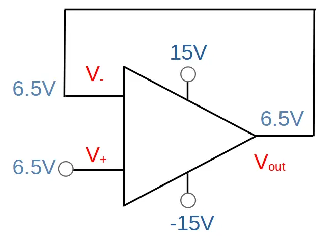
Now let’s increase the voltage on the non-inverting input to 6.5V:
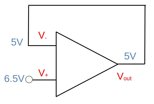
Now the operational amplifier will see a voltage difference between the inputs. Specifically, the voltage on the non-inverting input is greater than the voltage on the inverting input.
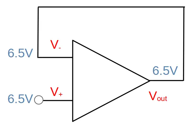
As a result, it will drive the output voltage up until the two inputs are equal to each other. This will happen when the output also equals 6.5V:
Example 3: Op-Amp Voltage Follower Input Voltage Decreased
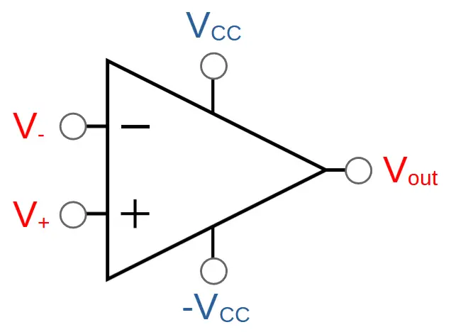
Now let’s see what happens when the input voltage is decreased. Specifically, let’s decrease it to a negative value (which is possible if -Vcc is also a negative value). To understand this, we have to remember that even though the op-amp only has two inputs, it is still powered by an external supply. The maximum (high) voltage that the op amp can output is Vcc, and the minimum (low) voltage it can output is -Vcc. These are sometimes also designated Vs+ and Vs-:
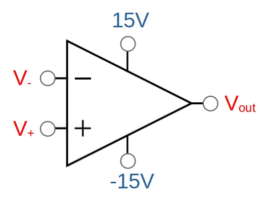
For this example, let’s supply the op-amp with a Vcc of +15V and a -Vcc of -15V:
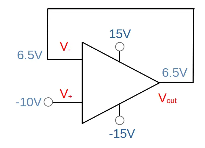
This is how it would look in the voltage follower circuit with 6.5V applied to the non-inverting input:
Now let’s drive the input voltage down to -10V:
What happens?
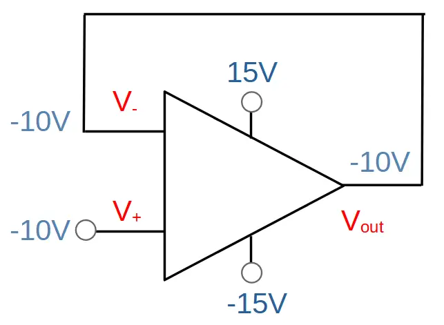
In this case, the op amp will detect that the non-inverting input is lower than the inverting input and will drive the output down. The output will decrease until signal on the inverting input is equal to the signal on the non-inverting input:
Op Amp Voltage Follower Saturation
In the previous examples we saw the operation of the op-amp voltage follower when the input voltage was within the voltage values supplied by the power supply. In other words,
-Vcc < V+ < VCC
The op-amp will saturate if the signal on the non-inverting input is either greater than Vcc or less than -Vcc. The output is limited to these values, so it won’t be able to increase or decrease the voltage any farther.
Example 4: Saturated Op-Amp Voltage Follower
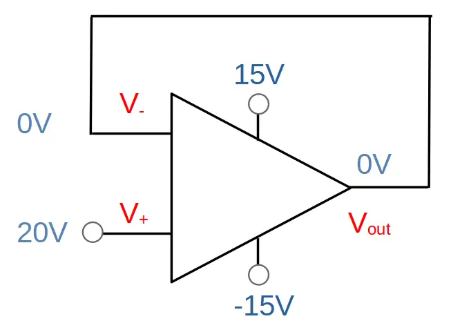
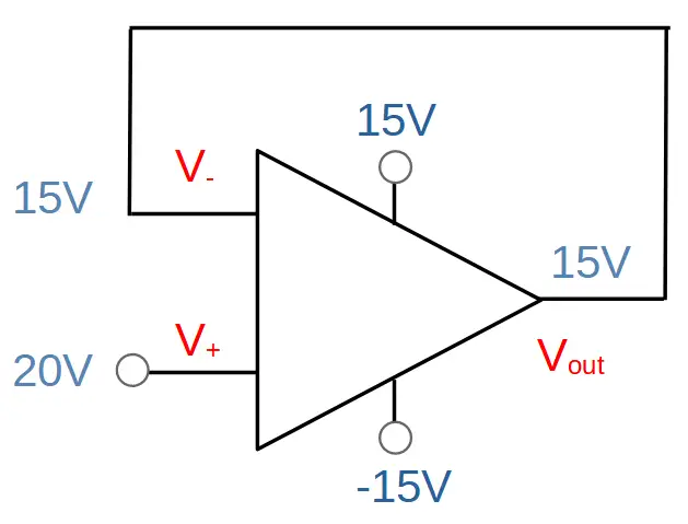
In this example, we will increase the voltage on the non-inverting input (V+) so that it is greater than the positive power supply voltage (Vcc). To make this example more clear, we will assume that we have just closed the circuit (startup) and the op amp has not had any time to react:
What will happen in this case?
Just as with the first three examples, the op-amp will sense that the signal on the non-inverting input (V+ at 20V) is greater than the signal on the inverting input (V– at 0V). It will drive the output voltage (Vout) up in an attempt to make the two inputs equal to each other.
Unlike the first three examples, however, the op-amp will not be able to make the inputs equal. It will increase the output voltage until it reaches the maximum voltage supplied by the power supply (Vcc).
Since Vcc is 15V, the op-amp will saturate at 15V:
This means that the saturated op-amp will not be able to reach a stable state, i.e. equilibrium. However, the output voltage itself is stable. It will sit at the maximum output voltage. In a real-life case, this maximum voltage will be slightly less than Vcc.
What Makes an Op-Amp Voltage Follower Useful?
What makes the op-amp voltage follower so useful is its impedance characteristics. The input impedance of the op-amp approaches infinite. This means that it requires almost no current to drive it. It also means that the voltage drop across the feedback wire connecting the output to the inverting input is negligible. In other words, since almost no current flows into the inverting input, there is virtually no voltage drop between the output and the inverting input.
Although the op-amp voltage follower doesn’t provide any voltage amplification, it is very useful as a buffer. This is because the input impedance is extremely high, while the output impedance is very low. This means that it can be very useful in cases where the circuit has different stages with impedance challenges, such as one stage’s input impedance loading the prior stage’s output impedance. This situation can cause a loss of signal transfer between the stages. The op amp can be used between the stages to improve the signal transfer because it will not load the first stage’s output impedance while still providing low output impedance for the second stage.
Voltage Follower, Buffer, Unity Amplifier
The op-amp voltage follower is also commonly known as an op-amp buffer and also as a unity amplifier. These names speak to three different characteristics of the same circuit.
‘Op-amp voltage follower‘ signifies that the output voltage follows the input voltage (on the non-inverting input). Whatever voltage you put on the non-inverting input, the op-amp will ‘follow’, i.e. produce the same output.
‘Op-amp buffer‘ describes the usage of the circuit as a buffer between two different stages. It reduces impedance-based issues between stages and therefore serves as a buffer between them.
‘Unity amplifier‘ describes the fact that it does not actually amplify the voltage. In other words, the gain of the amplifier is one (i.e. ‘unity).
Conclusion – Op Amp Voltage Followers
Op-amp voltage followers are useful circuits that utilize an op-amp with a simple feedback loop between the output and inverting input.
Despite having a gain of one, they are incredibly useful circuits due to their high input impedance and low output impedance. This allows them to be used as buffers between different stages in order to improve signal transfer.
Op-amp voltage followers are useful to learn in order to discover the properties of op-amps with a feedback loop. The functionality the op-amp voltage follower is essential to understand prior to learning more complex op-amp circuits.