Inductors
Key Points:
- Inductors oppose changes in the magnitude or directionality of electric current.
- Inductors store energy in a magnetic field. This magnetic field produces a voltage in response to a change in current.
- The voltage produced by an inductor opposes the change in current. Thus, an inductor works to oppose any changes in current.
What Is An Inductor?
An inductor is an electrical component that resists any changes in current. Any time the current is increased or decreased, or changes direction, the change will be opposed.
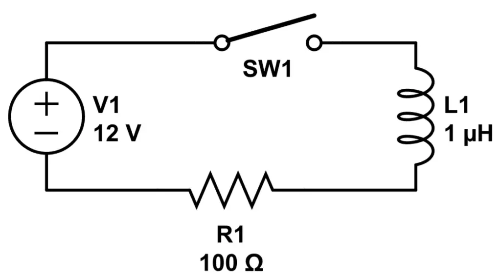
Let’s take a look at Figure 1, which has an inductor L1, with an inductance of 1 microhenry in series with 100 ohm resistor R1. We also have a 12V DC voltage source, and a switch (SW1) to open and close the circuit.
If we close the switch to energize the circuit, the inductor will prevent the circuit from immediately energizing to maximum current. Instead, it will oppose the current so that the current slowly increases to its maximum level. It will still rise to the maximum level dictated by Ohm’s Law, but it will do so slowly rather than immediately. The steady state current will not change again once it reaches its maximum level, which is the same as that of the series circuit without the inductor:
I_{max} = \frac{V_1}{R_1} = \frac{12V}{100\Omega} = .12AWhen you open the switch to open (de-energize) a circuit, the inductor will again prevent the change in current. This time, instead of the current dropping immediately to zero (0 Amps), it will slowly decrease.
This opposition to a change in current is called inductance.
What Causes Inductance?
It turns out that inductance is actually by something really cool:
Current carrying wires produce magnetic fields.
In order to understand how this works, we’ll need to learn about Ampere’s Laws.
Ampere’s Laws
In 1825, physicist Andre-Marie Ampere discovered that two wires carrying an electric current exert a physical force on each other. They either attract or repel each other, depending on how the wires are oriented. The force between two current carrying wires was named after Ampere; it’s called Ampere’s Force Law.
Ampere’s Force Law: Two current-carrying wires will experience a force of attraction or repulsion, depending on the orientation of the current.
Later, it was determined that the wires were developing magnetic fields around themselves. The magnetic fields of each wire in Ampere’s experiment were causing the wires to attract or repel each other, like magnets. It turns out that every current carrying wire develops a magnetic field, and this phenomenon was called Ampere’s Circuital Law:
Ampere’s Circuital Law: A closed loop with current passing through the loop will develop a magnetic field.
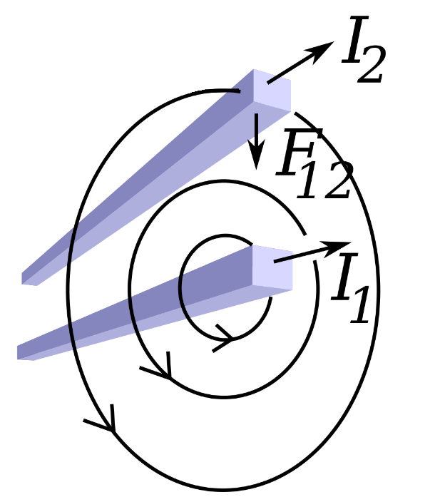
Figure 2 (above) shows two current carrying wires. One is carrying current I1, and the other is carrying current I2. Ampere’s Circuital Law tells us that both wires will have a magnetic field around them, generated by the current in each wire. The magnetic field for the bottom wire (carrying current I1) is shown; the magnetic field around the top wire is omitted for clarity. The top wire experiences a force, F12, due to the magnetic repulsion between the two wires.
Not shown in Figure 2 is the magnetic field produced by the top wire. It also produces a magnetic field that repels the field generated by I1. The force felt by the bottom wire would be called F21.
When a conductor is shaped properly (coiled), the resulting magnetic field is magnified significantly.
Faraday’s Law of Induction
So, Ampere’s Circuital Law tell us that a magnetic field will develop around a current carrying wire. What happens next?
If the current remains steady, not much. The circuit will function as if the inductor is not there, and the inductor will hold on to some energy that is stored in the magnetic field around it. The magnetic field does not change unless the current changes, and does not consume or release any energy.
But when the magnitude of current is changed, the magnetic field also changes in response.
In 1831, Michael Faraday observed that a voltage could be produced by causing wires with current to interact with a magnet. He performed several similar experiments. For instance, he observed that moving a magnet back and forth through coiled wired resulted in a voltage across the wires.
It was determined that the change in magnetic field (due to the motion of the magnet) caused an electromotive force (EMF), resulting in a voltage across the wires.
The change in the magnetic field produces a voltage that opposes the change. If the current is increased, the magnetic field will produce a negative voltage. If the current is decreased, the magnetic field will produce a positive voltage.
One important aspect of inductors is that because they oppose any change in current, they can be used to allow direct current (DC) while preventing alternating current (AC) from flowing beyond the conductor. However, the principle of induction is important to the functionality of the transformer, arguably the most important AC electrical device.
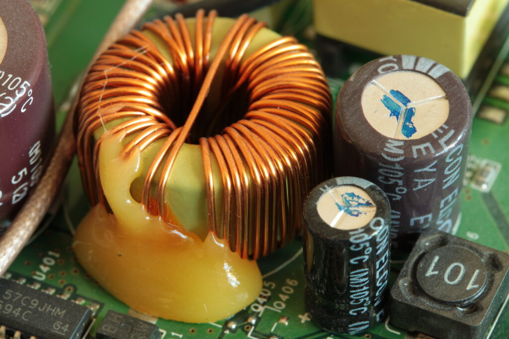
How Are Inductors Constructed?
Since even a simple wire has some inductance, a simple conductor can be made from a coiled wire. Increasing the inductance, i.e. the size of the magnetic field, is easy; just add more coils. The more coils, the greater the magnetic inductance. Most of the time, inductors use a core to maintain stability.
The two most common types of inductors are: (1) air core inductors, and (2) iron core inductors.
Air core inductors are made of a conductive coil wrapped around a plastic, ceramic, or any other nonmagnetic core. They tend to offer low inductance, but are highly efficient.
Iron core inductors use a conductive coil wrapped around a magnetic core. The magnetic core confines the magnetic fields produced, intensifying them around the coil. An iron core inductor can increase the inductance of a coil by over 1000x. The trade-off is that the iron core also produces losses, decreasing the efficiency.
Inductors can also be printed directly onto PCBs (printed circuit boards) by producing a spiral (conductive) trace.
Inductance
Inductors operate due to inductance, which is the tendency of a conductor to oppose any change to the current through it. Inductance is abbreviated with the letter L, and inductors are typically identified as LN, i.e. L1, L2, L3 etc.
All conductors feature some inductance, just as all conductors feature some resistance. Note the difference, however: resistance is a restriction of current in general, caused by inefficiency of conduction. Inductance the storage of energy in a magnetic field that opposes a change to the current, not the current itself.
The voltage induced by the magnetic field is often called ‘back’, or ‘counter’ electromotive force (EMF).
Inductance is defined as the ratio of the induced voltage (back EMF) to the rate of change of the current through the wire:
L = \frac{v(t)}{(\frac{di}{dt})}In this equation, L is the inductance and v is the voltage (back EMF) produced by the inductor. The quantity (di/dt) is the rate of change of the current with respect to time. It’s the derivative of the function of current, i(t) since in this case the current changes with time, i.e. current is a function of time.
Inductance can also be expressed as the ration between the magnetic flux and applied current. Magnetic flux simply means the amount of magnetic field generated and is abbreviated by the Greek letter phi, Φ:
L = \frac{N \Phi}{I}Here, N is the number of turns in the coil. Thus we can see that inductance is directly proportional to both the magnetic field produced and the number of turns in the coil.
If you wanted to build your own inductor, you can actually approximate the inductance easily by calculating the magnetic flux and solving for the inductance. We can magnetic flux Φ itself can be found if we know the number of turns in the coil (N), the length of the coil(l), the area of each coil (A), and the current we are applying:
\Phi = \mu_0 \frac{N}{l}IAWhere μ0 is the vacuum permeability (how easily a magnetic field permeates a vacuum) and is a constant, equal to 1.256 * 10-6 H/m.
Henry- the SI Unit of Inductance
Inductance is measured in the unit of ‘henry’, abbreviated by ‘H’. Henry is the SI unit of inductance and is a large unit. Common measurements are defined in millihenries or microhenries. One henry defined as 1 volt-second per Ampere:
1 H = \frac{1V\cdot s}{1A}Keep in mind that, like resistance, the inductance depends on the material and construction. Just as with resistors, it is more common to use a known inductor value to analyze a circuit, unless you are building a circuit and trying to determine the correct inductor to use. Given the fact that inductance is determined by the component, another useful way of thinking about inductance is by solving for the voltage:
1 V (back \ emf) = (1 H)\frac{1A}{s}In other words, you get one volt of back EMF for every current change of 1 Amp per second, when using a 1 henry inductor. Increasing the inductance will increase the back voltage in a linear fashion.
Inductance can be measured with an oscilloscope or with a special type of multimeter called an LCR multimeter.
The Right Hand Grip Rule
The direction of the magnetic field induced in a conductor by the current can be determined by the right hand grip rule. Magnetic fields form concentric circles around the conductor.
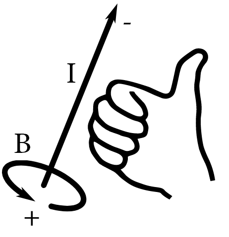
Mentally ‘grip’ the conductor with your right hand. Point your thumb toward the negative (-) terminal with your thumb pointed in the direction of current travel. This ensures that your thumb is pointed in the direction of current flow. The magnetic field will follow the direction of your fingers that are wrapped around the conductor.
The right hand rule can also be applied to find the direction of the magnetic field in an inductor.

In this case, we have an iron core inductor. The right thumb again points toward the negative terminal. The magnetic field will then be in the direction of the magnetic pole.
Uses of Inductors
Inductors are one of three pasive components used in electronics, along with resistors and capacitors.
They are commonly used to prevent AC signals while allowing DC to pass; when used this way, they are often called chokes.
Inductors are used in filters to separate signals and are widespread in radio equipment. They are also used in tuned oscillators and LC tank circuits and are common in power supplies to store and release energy, and also to eliminate ripple harmonics. They are used to store and transfer power in dc-ac and dc-dc power converters.