Kirchoff’s Voltage Law
Key Points:
- Kirchoff’s Voltage Law (KVL) states that for any loop in a circuit, the sum of voltages must be equal to zero.
- KVL is a restatement of conservation of energy.
- KVL allows us to write an equation that sets the total sum of voltages in a loop (positive for voltage ‘drops’ across circuit elements like resistors, negative for voltage sources like batteries) equal to zero.
Kirchoff’s Circuit Laws and Circuit Analysis
Kirchoff’s Voltage Law (KVL), also known as Kirchoff’s Loop Rule, states that the sum of voltages in any loop in a circuit must be equal to zero. It shares many similarities with KCL. They are both restatements of a conservation law (KCL is conservation of charge, KVL is conservation of energy), and they are both useful for setting up new equations that allow us to solve for an unknown variable.
Together, KCL and KVL are known as Kirchoff’s Circuit Laws, and are widely used in electrical engineering. They form the basis of modern circuit analysis. Instead of analyzing circuits by hand, computer programs are used to generate systems of equations using KCL or KVL. The computer program then solves the system of equations for all of the unknown parameters.
What is KVL?
Let’s start with a simple example of a resistive series circuit. This circuit has a single loop, with the current path shown by blue arrows.
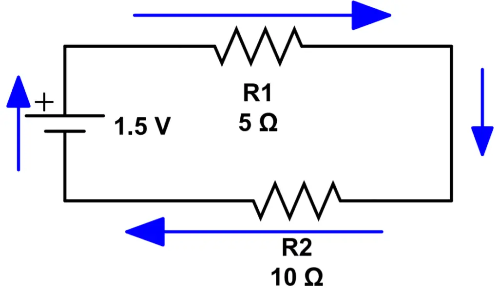
KVL states that the total voltage in the loop must add to zero. To make the math easier, the convention is to define voltage drops as positive and voltage sources as negative. This is an important point so be sure you understand what we’re talking about. It means that the 1.5V battery actually supplies a negative voltage. The resistors produce a voltage drop that is considered a positive voltage.
Let’s call V1 the voltage drop across R1, and V2 the voltage drop across R2. Let’s write out KVL for this system and see if you can follow along to use Ohm’s Law quickly calculate the current:
-1.5V + V_1 + V_2 = 0 \\ -1.5V + IR_1 + IR_2 = 0 \\ -1.5V + I(R_1+R_2)=0 \\ I(R_1+R_2)=1.5V\\I = \frac{1.5V}{R_1+R_2}=\frac{1.5V}{5\Omega+10\Omega}=\frac{1.5V}{15\Omega}=.1AUsing the current we can find the individual voltage drops across each resistor:
V_1 = IR_1 = (.1A)(5\Omega) = .5V \\
V_2 = IR_2 = (.1A)(10\Omega) = 1V\\
We can quickly check to ensure our math is correct by verifying that the sum of all voltages equals the applied voltage:
V_{battery} = 1.5V = V_1+V_2