Peak Detector
A peak detector is a circuit that measures the peak voltage of a waveform.
Peak detectors are highly useful building block analog circuits. There are many situations in which it is helpful to measure the peak signal of a waveform.
Simple but relatively effective peak detectors can be made from as little as two components: a single diode and a capacitor.
The circuit makes use of the storage function of the capacitor as a type of memory. We assume that the capacitor will store electric charge, and therefore maintain a voltage level indefinitely until the time of measurement.
The voltage across the capacitor can be measured in order to ascertain the highest peak voltage that the circuit has been exposed to.
Peak Detector Circuit
A peak detector is a simple circuit that requires only two components, a diode (D1) and a capacitor (C1).
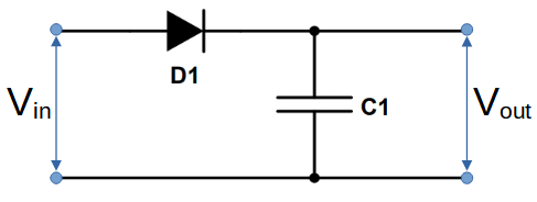
The purpose of the capacitor is to store energy and function as a voltage source, and the function of the diode in this circuit is to prevent the capacitor from discharging through it.
The diode is placed in series between the input and the capacitor, and output of the circuit is measured across the capacitor.
An input signal with a varying voltage magnitude can then supplied to the circuit.
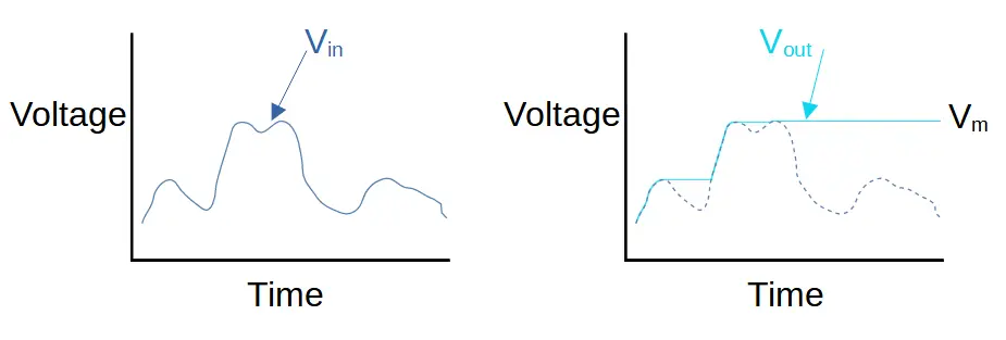
The capacitor will accumulate charge and ‘store’ the highest voltage in the input waveform. It produces Vout, as shown above (on the right). Note that Vout always stays at the highest point of the input waveform.
We assume that until the time of measurement, that there is no connection across the capacitor. Prior to measurement, the capacitor is prevented from discharging by an open circuit on one side and a reverse biased diode on the other side.
For example the left side of the image above shows an input voltage signal Vin that changes in magnitude over time.
The voltage across the capacitor (Vout) increases when Vin increases. This is caused by the charging of the capacitor.
Whenever Vin begins to decrease, the capacitor starts to function as a voltage source in the circuit. It applies a reverse bias to diode D1, preventing the capacitor from discharging. It maintains the same voltage level even as Vin fluctuates below the maximum voltage.
The right side of the image above shows the output voltage Vout. Vout increases when Vin increases, and remains at the last high point when Vin decreases. When Vin increases above the last high point, Vout again increases to the last high point.
The highest point achieved is Vm, and this will remain the output unless either a higher voltage is applied or the capacitor is allowed to discharge.
How the Peak Detector Works
The peak detector operates by storing charge in the capacitor. When a varying voltage is supplied to the circuit, the capacitor will ‘store’ the highest voltage (potential difference) that has been supplied to the circuit.
In order for the capacitor to store the charge effectively, it must be allowed to charge but the capacitor cannot discharge. In other words, a one-way ‘valve’ is required that allows the capacitor to charge without allowing it to discharge.
A P-N junction diode is used to achieve this. When a forward voltage is placed across the circuit, the diode allows current to flow in the positive direction. Current must also flow through the capacitor, which only occurs while the capacitor is charging or discharging.
The capacitor’s tendency to charge or discharge is based on the applied voltage; if the voltage is changing, then the capacitor will try to charge or discharge. If the voltage is constant, than the capacitor will quickly charge (or discharge) and achieve steady state.
But if the capacitor can’t discharge, then the capacitor will continue to store the electric charge, with a voltage of Vmax across
The charge across the capacitor produces a voltage when measured.
Using a Bleeder Resistor in the Peak Detector
The circuit above will hold charge indefinitely (if we disregard leakage). Sometimes, however, we want the detector to reset at some interval. In this case, we can use a bleeder resistor in parallel (R1 in the circuit below) to discharge the capacitor.
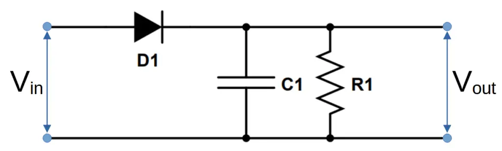
The discharge rate is dictated by the time constant RC (the resistance of the resistor times the capacitance of the capacitor).
The time required for the capacitor to discharge to 99% will occur at 5 times the RC time constant, i.e. 5RC.
Limitations of Capacitor Peak Detectors
The primary limitation of this peak detector circuit is that leakage through the capacitor will eventually cause it to discharge. Depending on the capacitor, this could occur over a relatively short period of time.
In addition, the voltage recorded by the peak detector is reduced by the forward voltage of the diode. This means that all peak detectors have an inherent efficiency loss.
Capacitor as Memory
The peak detector circuit introduces the concept of using a capacitor as a memory storage device.
One advantage of capacitor as memory is that the capacitor can store a full range of voltage rather than a binary state ‘0’ or ‘1’. For example, it can store the values of 3 or 5 or 8.972. The downside is that leakage current