Diodes
What are Diodes?
Diodes are one of the most common electrical components, and are found in virtually every electronic circuit. Diodes are electronic components that allow electric current to flow in one direction while preventing current from flowing in the opposite direction. They are the electrical equivalent of a mechanical check valve (also known as a one-way valve) because they only allow current to flow in one direction.
Diodes have one input and one output, making them two terminal devices like resistors. Unlike resistors, diodes have polarity, meaning that they will only function when placed in the circuit with the correct orientation. If a diode is installed with the wrong directionality, it will perform exactly opposite the way you want; it will prevent the current that you do want, while allowing current to flow from the wrong direction.
An ideal diode has zero resistance to current in one direction, and infinite resistance to current in the opposite direction. Real-life diodes are never ideal, but by selecting the right diode for the right application, we can often ignore the non-ideal characteristics of diodes.
The first diodes were made with vacuum tubes, which are still sometimes used for high power applications. Diodes are actually the simplest type of vacuum tube device. But the most common diodes today are solid state semiconductor diodes made from a doped silicon substrate. These devices are typically constructed from specifically designed P-N Junctions.
Diodes may also be called rectifiers, because they ‘straighten’ the direction of current flow. Typically a rectifier is a diode that is used to convert an alternating current to a direct current. One of the most common applications of diodes are in AC to DC rectifier circuits. Rectifier circuits use a combination of diodes to minimize losses while converting an alternating current to a direct current.
How do Diodes Work?
Diodes allow current to pass when they are placed in a forward-bias configuration but prevent current from passing while in the reverse-bias configuration.

In a diode, current can only flow from the anode to the cathode:
Anode: The positive terminal of a circuit component (like a diode).
Cathode: The negative terminal of a circuit component (like a diode).
When the positive terminal of the diode (the anode) is connected with the positive terminal of the power source, this configuration is called forward bias. Forward bias actually refers to the degree to which a forward potential is placed across the diode. A larger forward bias means that a higher electric potential difference (voltage) is placed across the diode, with the voltage pushing current from the anode to the cathode. A reverse bias would refer to either the diode being placed in the opposite configuration, or having a negative voltage placed across the diode. In either case, a reverse bias is a voltage that is trying to push current from the cathode to the anode (i.e. opposite the ordinary direction in which current flow is allowed through the diode).
When a forward-bias is applied, current flows from the anode through the diode and exits the cathode, which is connected with the negative terminal of the power source. Electron flow is always opposite current flow. So in a diode what is physically taking place is that the electrons are travelling from the cathode to the anode.
So an ideal diode is designed to allow current to flow only when a forward bias is placed across it, and to prevent current flow when a reverse bias is used.
Two Fundamental Types of Diodes
There are two primary classes of diodes; vacuum tube (also known as thermionic) and solid state. They have different functionalities that allow each one to operate, and we will briefly cover both as an understanding of one is helpful to understanding the other.
Vacuum Tube Diodes
Vacuum tube diodes use a heated metal to inject electrons from the cathode to the anode thus generating current from the anode to the cathode. The schematic representation provides a fairly good basis to understand how this works:

In this figure, the circle represents a vacuum tube. The cathode is on the bottom of the tube, with its’ terminal connection point sticking out to the left. The anode is at the top of the vacuum tube. Below the cathode is an ‘n’ shaped heater, which heats the cathode. When the cathode reaches a high enough temperature, it begins to eject electrons, which are caught by the anode at the top of the tube.
From this simple explanation, we can understand why the vacuum tube diode only allows current to flow in one direction. This is because the anode is not heated; it simply can’t eject electrons the way that the cathode can.
Solid State Diodes
Solid state diodes function on an entirely different principle, which is that of a P-N Junction.
In a P-N Junction, a semiconductor substrate is doped so that one side of the junction has free electron holes, which is called a ‘P-type’ material. This is accomplished by adding atoms that have one less electron than the atoms of the bulk semiconductor crystal. The other side of the junction has free electrons and is called an ‘N-type’ material. This is done by adding atoms that have one more electron than the atoms of the semiconductor crystal.
At the junction itself, a depletion region forms through which current can’t pass. If a voltage is applied in one direction, the depletion region will shrink and allow current. If a voltage is applied in the other direction, the depletion region will grow and the P-N Junction will resist current even more.
Most semiconductor diodes are versions of a P-N Junction. A diode in forward-bias has it’s P-side connected with the positive terminal of the power source and its’ N-die connected with the negative terminal of the power source.
Current-Voltage Curve (I-V Curve) of a Diode
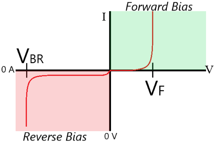
Like most circuit components, actual diodes don’t behave ideally. With a forward-bias, a diode will only conduct significantly when a certain voltage is applied; this is known as the threshold, or cut-in voltage. This is one major difference between ideal and actual diodes.
The other major non-ideal behavior of diodes is called the breakdown voltage. If a high enough reverse bias is placed across the diode, it will begin to allow current to pass from the cathode to the anode.
Forward Voltage, aka Threshold Voltage, aka Cut-In Voltage
Diodes will only function properly when a minimum forward voltage is applied.
This voltage is known as the forward, threshold, or cut-in voltage, and is most frequently designated VF. The threshold voltage corresponds with the voltage required to push charge carriers through the depletion region. Click here to learn about the depletion region in a P-N Junction.
At very low voltages, a diode may not allow current to pass at all. At higher voltages that are below the threshold voltage, a diode exhibits significant resistance while still allowing some current to pass. Above the threshold voltage, the resistance drops and the diode allows current to pass with only a small voltage drop across it.
Breakdown Voltage
Diodes also display non-ideal behavior in reverse bias. A diode will allow current to pass while in reverse bias if a large enough negative voltage is placed across it. This phenomenon is called reverse bias breakdown, and the voltage at which it occurs is referred to as the breakdown voltage, VBR.
In some cases, this is actually intended, while in others it can represent a failure of the diode itself.
When choosing the right diode for a circuit, the breakdown voltage is one of the most important factors. The maximum possible reverse bias across the diode must be calculated. Then a diode that has a higher breakdown voltage than the highest possible reverse bias is used as a primary parameter for selection.
Where/How are Diodes Used?
Diodes perform many functions, and are found in many different types of circuits. Diodes are not ‘one type fits all’. Although all diodes share the basic functionality of a diode, different types of diodes are engineered for specific applications.
One of the most common uses of diodes is in AC-DC conversion. An efficient rectifier circuit will effectively convert alternating current into direct current with minimal loss of power.
Diodes are often used to protect circuits by preventing current from travelling in the wrong direction.
Light Emitting Diodes (LEDs) provide the rectifying functionality of a diode while also emitting light. This can be useful as an indicator of circuit performance or functionality, or may be the primary intent as in the case of LED lighting. LEDs are also used in most modern televisions, in which they provide the lighting for each pixel.
Types of Solid State Diodes
There are several different types of solid state diodes that have functionalities which differ slightly from that of ordinary, P-N junction diodes.
Light Emitting Diodes (LEDs)

LEDs, or Light Emitting Diodes, are one of the most common electronic components. They function as rectifiers like ordinary diodes but also emit light as current passes through them. The light that is emitted depends specifically on the materials and construction of the diode.
In all P-N junction based diodes, there is a release of energy as electrons and holes recombine at the center of the junction when a forward bias is applied. LEDs take advantage of this energy release by engineering the diode so that the energy is within the frequency band of visible light.
Unlike an incandescent light source, they only emit light at very specific frequencies. This makes them extremely efficient at converting electrical energy into light, and also allows them to operate at much cooler temperatures than most traditional light sources.
Laser Diodes (LDs)
Laser diodes are at the heart of most commercially available lasers, including the laser pointers commonly used at work and home.
Laser diodes are very similar to LEDs in terms of how they operate. Like LEDs, laser diodes generate light via carrier recombination at the junction. However, laser diodes produce a specific frequency of light due to a phenomenon called stimulated emission, in which one photon of light stimulates the emission of more photons of the same exact frequency.
In addition, the light produced by an LD is confined and then focused so that it produces a single collimated beam of light.
Zener Diodes

Zener diodes are designed to be used with a reverse bias. They have a carefully selected breakdown voltage that allows current to pass if a high enough reverse bias is applied. Zener diodes are also designed to withstand this reverse bias without being damaged by it.
Photodiodes

Photodiodes are somewhat different from other diodes. Where most diodes are constructed to prevent light from reaching the junction, photodiodes use the energy from light to generate a current. Rather than functioning as a type of rectifier, photodiodes are sensors that absorb light, using the energy from the light to drive carrier recombination at the junction.
A photovoltaic solar cells is perhaps the most common example of a photodiode.
How to Select a Diode
There are several helpful steps in determining the right diode to use in a circuit:
- Determine the maximum reverse bias across the diode. The breakdown voltage of the diode must be higher than this figure.
- Calculate the maximum forward current. The diode must be rated for at least this amount of current.
- Determine the maximum voltage drop allowable across the diode.
Use the combination of these parameters to determine the specifications of the diode to be used.