Electric Circuits
What Are Electric Circuits?
Electrical systems are made of electric circuits. An electric circuit is a system, or network, of interconnected electric components. Circuits allow us to use electricity in helpful ways. Electricity, or more specifically, electric current, flows through a circuit and the different components that make it up.
Circuits are often referred to as networks because of the interconnected nature of the different components.
Electric circuits can be made of many different types of components, and are the basic building blocks of all electrical systems.
There are two main aspects to consider when we are looking at any electric circuit:
1) The components that are included in the circuit.
2) The interconnections between the components, i.e. the way in which the components are connected together.
We use electric circuits every day in our daily lives. When you use a switch to turn on a light, you are completing a circuit from your power supply (probably a circuit breaker panel), to the switch, to the lightbulb, and back to the power supply. Digital devices like phones or laptops contain millions of electric circuits that are used to process data.
Without circuits, we wouldn’t be able to use electrical systems. There wouldn’t be an internet, cell phones, or even home appliances. You wouldn’t even be able to explore this awesome website! Our world would be a much different, somewhat less interesting place.
An electric circuit with two resistors in parallel.
What are Electric Circuits?
Let’s start by defining an electric circuit, also called an electrical network.
You can think of an electric circuit as a loop, or set of loops, around which electric current, i.e. electrons, can flow. If we give an electron a ‘push’ around the circuit, it pushes the electron next to it, which then pushes the electron next to it. It’s kind of like billiards but all the balls are stuck on a track and there isn’t much space between them. Giving a single electron a push will therefore push all of the electrons in the whole circuit.
Keep in mind that electrons don’t actually ‘touch’ each other. Instead, the negative charge in one electron repels the negative charge in its’ neighbors, thanks to the electric field around the electron.
Electron flow is the most common type of electric current in circuits. In fact, when we use the term ‘electric current’, we will almost always be talking about electrons flowing through a circuit. This is sometimes referred to as electron current. However, it is also possible to have an electric current due to the flow of ions, which are atoms that have unequal amounts of electrons and protons (i.e. charged atoms).
A Model Circuit
Let’s look at a model of a circuit to see how electrons flow:
This model circuit is basically just a closed loop of wire. The outer black box represents the wire, which is a conductor made out of metal. The metal has electrons that are ‘free’ to move from one side of the wire to the other and around the loop. When we connect the wire into a loop, like we show above, the electrons can now travel through that loop. We can almost imagine the electrons moving around the loop forever.
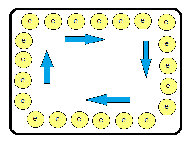
If the wire is a superconductor ( a material with zero resistance), the electrons really could move around this loop forever. In real life, conductors (like our metal wire) have some resistance, which means that as electrons move through the metal, they bump into things like atoms and microscopic cracks in the metal along the way. As the electrons bump into obstacles, they lose some of their energy in the form of heat. so we have to keep pushing on the electrons with a power source.
Open and Closed Circuits
In order for electricity to flow through a circuit, it must have somewhere to come from and somewhere to go. If the loop is broken, the electrons won’t be able to move anymore. This is called an open circuit.
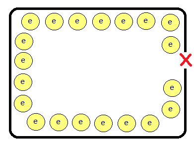
Let’s cut the wire on the right hand side and see what happens in the circuit.
The result is like a traffic-jam of electrons.
The electrons stop at the place where we cut the wire because they can’t go any farther. When they stop, the electrons behind them bump into the stopped electrons and can no longer move either. All of the electrons in the wire came to a screeching halt (stop). An open circuit prevents current from flowing anywhere in the circuit.
A circuit is called closed if there is a complete current path. If we re-attach the wire in the above circuit, electrons will again be able to flow through the loop of wire.
A switch (like a light switch) works by opening or closing a circuit. To turn a light on, you use the switch to close the circuit. In order to turn the light off, you use the switch to open the circuit.
The Structure of a Circuit
While the example of electrons travelling through a loop of wire is useful for visualizing how a circuit works, real circuits are a bit more complex.
Electric circuits are made of three things:
- A power source. Circuits can have multiple power sources, but they must have at least one.
- Components. Circuit components do useful things in the circuit.
- Connectors like wires or conductors. Connectors are used to connect the power source(s) and components together.
Technically, power sources can be circuit components themselves, but it can make things easier to differentiate. Unless we’re using a discrete, self contained power source like a battery, the circuit is usually powered by another circuit, which is often powered by another circuit and so on.
Think about how many circuits are in between a simple device like a toaster, which plugs into a wall outlet, and the original power source which is probably a large generator in a power plant miles away. In between there are lots of components like switches and transformers and transmission lines that allow the electricity to travel from the power plant to your home. The whole system can be broken down into many individual circuits, with the original power source (the generator) abstracted away. This is kind of a miracle in itself; we can just pretend that the source is a single component that powers our toaster.
Speaking of abstraction, it often helps to be able to visualize circuits, especially those that are complex. Luckily, engineers developed a standardized system that allows us to illustrate and understand circuits more easily. Illustrations like this are called circuit diagrams.
Electric Circuit Diagrams
Circuit diagrams are ways to represent electric circuits in two dimensions (i.e. on paper or a screen). The most common type of diagram is known as an electrical schematic, which uses standard symbols to show a circuit. These symbols are abstracted versions of their physical selves. If we know what a component does, we don’t need to know how it works. For example, two resistors can be made with totally different materials and methods of construction, but both can be represented by the same exact symbol if they both have the same value of resistance.
When looking at a circuit diagram, there are a few things to keep in mind. First, diagrams don’t show electrons in the wires. The existence of electrons throughout the entire circuit is implied by the circuit itself. Second, real circuits also require a power source to move the electrons. Circuit diagrams use symbols to help show us what is supplying power to the circuit, and which side is negative and which is positive. Let’s look at a few examples to get comfortable with circuit diagrams.
For example, a circuit diagram for an electric circuit consisting of a battery and a loop of wire would look like the image on the right.
The symbol for a battery consists of a long line indicating the positive terminal, and a shorter line indicating the negative terminal. In this case, the positive and negative terminals of the battery are connected to each other with a wire, as represented by the black loop connecting the two terminals of the battery.
We can also see that the battery is rated for 1.5 V (volts).
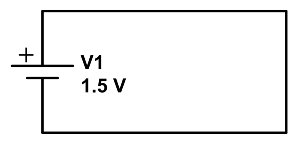
A circuit like this could actually be dangerous, because there isn’t enough resistance in the wire to prevent the current from exceeding the rating of the wire. This is called a short circuit, and can lead to sparking, heat, fire, or even explosion.
It’s important to always keep in mind that circuits require resistance to prevent a short circuit.
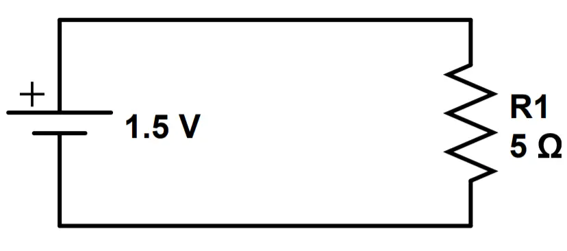
Luckily, this is an easy problem to fix. All we have to do is add a resistor to the circuit. A resistor functions by reducing current flow, so it’s great for this purpose.
If you look at the circuit diagram, you will notice a new symbol that looks like a zig-zag line and is labeled as R1. This is a resistor. Our circuit is no longer short-circuited thanks to R1.
This simple circuit diagram shows a complete circuit. It contains (1) a 1.5 V battery as a power source, (2) a component- resistor R1, and (3) wires connecting the battery and resistor.
Understanding Circuit Diagrams
You can think of a circuit diagram as a blueprint for an electric circuit. It shows us what the circuit is made of and how it everything in the circuit is connected.
The only difference is that diagrams don’t actually show us how the circuit looks in real life. They are usually laid out in a way that makes the circuit logical and easier to follow.
In real life, a wire that looks really long on a diagram might actually be short, and vice versa. In fact, the connection might not be a wire at all. It could be a solid metal bus bar or a conductive path printed directly onto a PCB (printed circuit bard).
The point is that the circuit diagram does show us how the contents of a circuit and how all of the components are connected to each other.
Electric Circuit Components
Electric circuits are made of components and the connections (i.e. wires) between those components. From this perspective, an electrical circuit is really a series of interconnected components that do different things. Components are also referred to as circuit elements when they are placed into a complete circuit.
Throughout this course, you will encounter many different types of components. Each is different; they have different uses, materials, and construction, and use different electromagnetic principles to function. That’s why a great way to learn about electronics is to learn about the components, and then to learn about them in different combinations.
Here’s a short list of common circuit components and their functions:
Resistors: Control current flow by reducing it precisely.
Capacitors: Store and release electric charge.
Inductors: Oppose a change in the magnitude or direction of current.
Transformers: Increase or decrease an AC voltage or current.
Diodes: Only allow current to travel in one direction.
LEDs: Diodes that emit light as current passes through them.
Transistors: Act as either switches or amplifiers.
Integrated Circuits: Pre-packaged circuits that perform a huge range of functions. They include many of the components previously mentioned.
Active and Passive Circuits
Components can be divided into two categories: active and passive.
Active components add energy to the circuit. They can be voltage sources (such as batteries), or semiconductor components like transistors.
Passive components don’t add energy to the circuit. They include every component that isn’t active, like resistors, capacitors, inductors, and diodes.
Electrical vs. Electronic Circuits
Another classification is based on electrical vs. electronic systems, or circuits.
Electrical systems control current flow using passive components like resistors, capacitors, and inductors. These systems use classical electrical engineering in order to function.
Electronic systems control current flow using active, typically semiconductor based devices like transistors and integrated circuits. These systems control current by using amplification and rectification as well as resistance, capacitance, and inductance.
Series and Parallel Circuits
Circuits can be arranged in series, in parallel, or in a combination of the two. A series circuit has only one path for current to follow, while a parallel circuit has multiple current paths.
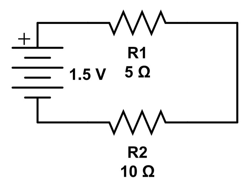
The image on the right shows two resistors, R1 and R2, connected in series with a 1.5 volt battery.
This circuit is called a series circuit because there is only one path for current to follow. Current must leave the battery at the positive terminal, travels through R1 and then R2, and then re-enters the battery at the negative terminal.
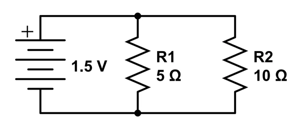
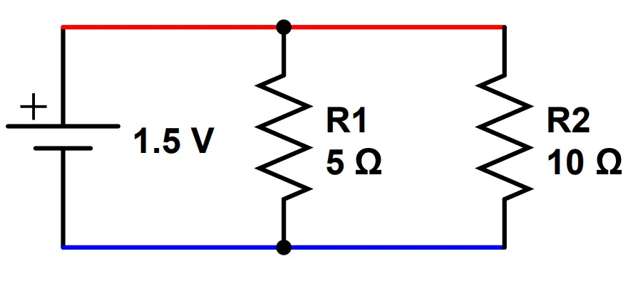
We can re-arrange the same components to form a parallel circuit. In the image on the left, we have now connected R1 and R2 in parallel with each other.
This is called a parallel circuit because current can travel simultaneously through the parallel paths offered by R1 and R2. Current leaves the battery at the positive terminal, travels through both R1 and R2 at the same time, and then re-enters the battery at the negative terminal.
Components behave differently when they are arranged in different configurations. For instance, resistors increase resistance when placed in series but decrease resistance when placed in parallel. Capacitors do the opposite.
This is why we learn each type of circuit on its’ own, and then combine them, when learning about the different components and arrangements.
You can learn more in our lesson on series and parallel circuits.
AC and DC Circuits
Electric circuits can have different properties depending on how electrons move in the circuit. A common example is that of alternating current (AC) vs. direct current (DC).
Direct current (DC) circuits are more simple than alternating current (AC) circuits. Current moves in one direction and stays at the same level. The electric circuit is in a steady-state which makes things fairly easy to understand. DC circuits are really common in electronics, so don’t be fooled into thinking that they are ‘beginner circuits’. All battery powered devices and logic based devices use DC circuits. Basic DC circuits are covered in depth in Module 3.
AC circuits are a bit more difficult to understand. The current changes over time and even changes direction! Depending on the circuit, an alternating current circuit can be more difficult to understand. However, they are really useful in a wide variety of applications including power generation, transmission, and radio. Transformers are one of the most useful electric components, and they only work with AC circuits. AC circuits are covered in Module 4.
Electric Circuits Problem Examples
Problem # 1
Question: What is the difference between an open circuit and a closed circuit?
Answer: An open circuit contains a break that prevents current from flowing through the circuit. A closed circuit has a complete loop, allowing current to flow.
Problem # 2
Question: What is an active component?
Answer: An active component is one that adds energy to the circuit. In contrast, a passive component does not add energy to the circuit.
Problem # 3
Question: What is the difference between DC and AC?
Answer: DC stands for ‘direct current’, meaning that current only travels in one direction through the circuit. AC stands for ‘alternating current’. In an AC circuit, current travels in one direction and then alternates, travelling in the opposite direction.
Let’s continue on to Lesson 2: Electric Power Sources!