Introduction to Electrical Resistance
Electrical resistance is the property of a material or system that determines its opposition to the flow of electric current. The greater the resistance, the less conductive that material is.
Resistance is used intentionally in circuits by incorporating resistors, which are one of the most common electrical components.
But resistance isn’t only limited to resistors. Every single component, wire, and connection point in a circuit increases resistances if only a little.
Resistance is also significant when wiring larger projects, or for home, auto, boat, and industrial wiring. The resistance of a wire limits it’s current carrying ability and depends on the thickness (called ‘gauge’) of the wire. Selecting the right gauge wire is important for safety and functionality.

Resistance affects circuits in several ways. First, every single component and wire in a circuit has some resistance. Second, resistance is used intentionally in virtually every circuit; resistors are one of the most common electrical components. Third, every point of contact between different surfaces or materials in a circuit introduces some contact resistance.
In this lesson, we’ll explore the concept of electrical resistance in detail including what it means, where it comes from, and how it is used to our advantage in circuits.
What is Electrical Resistance?
Electrical resistance is the property that determines how easily current flows through a given piece of a material. Because circuits are carefully designed systems, the property of resistance is super important.
As we learned in electrical properties of materials, some materials are conductors, some are semiconductors, and others are insulators.
Conductors have low resistance and allow electric current to travel through them with high efficiency. Conductors are normally made of metal like copper or aluminum.
Insulators have very high resistance; they do not allow electric current to flow without a lot of energy, i.e. high voltage. Insulators are made of polymers or rubber. Air is a decent insulator and vacuum is the best possible insulator.
Semiconductors have a mid-range resistance that is between the resistance of conductors and insulators. It only takes a little energy for a semiconductor to conduct electricity.
You can find a complete table of resistivity and conductivity of many materials here.
Almost no common materials are perfect conductors, so electrical resistance plays a role in every part of a circuit. including conductors like copper wires. In other words, every component in a circuit contributes some resistance.
Perhaps even more importantly, electrical resistance is used in almost every circuit in order to control current or voltage. Devices with specific values of electrical resistance are called resistors. Resistors are incredibly useful because they can be used to design sections of a circuit with lower voltages or currents, or to reduce current in the entire circuit. This means that you can take a given voltage source (like a wall outlet or a battery) and use electrical resistance to determine output voltages and currents.
Ohm: SI Unit of Electrical Resistance
The SI Unit for electrical resistance is the Ohm, which is represented by the Greek letter Omega ‘Ω’.
The Ohm is defined as the resistance between two points on a conductor on which one volt of potential is applied, which results in a current of one amp:
1 \Omega =\frac{1V}{1A}This relation is also called Ohm’s Law. Ohm’s Law is telling us here that if we apply a 1 volt battery across a 1 ohm resistor, we will generate one amp of current. It takes one volt to produce one amp of current through a one ohm resistor.
You may note that the unit of measure for electrical resistance, the Ohm, is defined through Ohm’s Law.
You’ll notice that Ohm’s Law also tells us that resistance is the ratio between voltage and current. Consider a circuit with a fixed voltage source. A resistance of 1 ohm gives us a 1:1 ratio between voltage and current. A resistance of zero gives us an infinite current, and a resistance of infinite gives us a current that is equal to zero.
Measuring Resistance
Resistance can be measured using a multimeter or an ohmmeter using the following steps:
- Turn off all power to circuit. If the circuit contains charged capacitors, discharge them before proceeding.
- Turn multimeter to resistance mode, usually marked with an Omega sign (Ω).
- Insert the black test lead into the COM jack, and then insert the red test lead into the jack labelled with an Ω sign. This jack will often have a combined function, so it may be labelled as ‘VΩ’ or ‘Ω CAP’ or something similar.
- Connect test leads to the measurement points. This may be on either side of a resistor, or a series of resistors, or at two different points in a circuit.
- Remove and disconnect red test lead, then black test lead, and turn multimeter off.
Resistivity
Except for superconductors (found mostly in labs), every material has some resistance. The resistance of materials is generally expressed by the property of resistivity.
Materials are classified in terms of resistance, with the property of resistivity used to measure the resistance of a given block of material. Resistance is a general, point-to-point measurement, and resistivity is a measure of the resistance of a material of a certain size.
Conductors have low resistance, insulators have high resistance, and semiconductors exhibit resistance that is somewhere between that of conductors and insulators.
| Material Type | Resistivity | Conductivity |
| Conductors | 10-8 | 107 |
| Insulators | 1016 | 10-15 to 10-25 |
| Semiconductors | 10-3 to 103 | 10-8 to 10-4 |
| Superconductors | 0 | ∞ |
Even conductors have some resistance. For instance, silver has the least resistance of any metal. Silver has about 35% less resistance than gold. Unfortunately, silver is expensive and also tarnishes, becoming less conductive over time. Copper is the second most conductive metal, and is commonly used because it is cheaper than silver.
| Material | Resistivity (at 20°C) | Conductivity (at 20°C) |
| Silver | 1.59 * 10-8 | 6.30 * 107 |
| Copper | 1.68 * 10-8 | 5.96 * 107 |
| Annealed Copper | 1.72 * 10-8 | 5.80 * 107 |
| Gold | 2.44 * 10-8 | 4.11 * 107 |
| Aluminum / Aluminium | 2.65 * 10-8 | 3.77 * 107 |
Where Does Electrical Resistance Come From?
The primary factor in any material’s ability to conduct electricity is its’ outermost electrons, i.e. the valence electron configuration. Valence electrons are the electrons that occupy the outermost electron shell of the atom, also known as the valence shell.
The valence electron configuration determines how many electrons are in the outer band or shell of the atom, and how tightly those electrons are bound to the atom’s nucleus.
Atoms with a single atom in the valence shell are the most electrically conductive since an atom with a single outermost electron holds onto that electron more loosely than an atom with more electrons in the outermost shell.

When a voltage is applied, an atom with only one valence electron will lose its’ weakly bound outer electrons much more easily than other atoms, explaining why metals with a single valence electron (silver, copper, and gold) are the most electrically conductive of all elements. Of these, silver has the lowest resistance but since it also tarnishes, it is usually not as good of a choice as gold or copper. The resistance of gold is lower than that of copper, but the high cost of gold leads most designers to select copper as the material of choice. However, for projects requiring a lot of metal, a high grade of aluminum is often used.
Crystallographic Defects and Electrical Resistance
However, other factors can have a significant effect on resistance, and also dictate how much resistance even highly conductive materials can have. The primary factor is scattering, which is the degree to which an electron is deviated from a straight path of travel within the material. The longer an electron can travel in a material without being scattered, the lower the resistance.

Metals are crystalline solids, meaning that they have an ordered structure with a unit cell that repeats along it’s entire structure. In general, any defect or interruption of the perfect crystalline structure, will increase the electrical resistance of that material.
Crystalline solids are rarely single crystals (monocrystalline); instead they are typically polycrystalline and feature many small crystallites, or grains, each with a slightly different orientation. In between each crystallite and its neighbors are grain boundaries, areas that have higher energy than the inner crystalline material and that tend to scatter electrons, light, and even heat. Electrons are deflected off each grain boundary; the voltage still compels them to travel toward the positive terminal, but their direction tends to change as they encounter grain boundaries.
In addition to grain boundaries, metals also contain many other defects that are typical of crystalline solids, including missing atoms (vacancies), contaminant atoms (interstitial atoms) and disruptions of the crystal structure within single crystallites (dislocations). Essentially any deviation from a perfect crystal will cause electrons traveling in the metal to alter their trajectory, slowing electron travel and thereby increasing electrical resistance.
Temperature and Electrical Resistance
| Material Type | Resistance With Higher Temperature | Notes |
| Conductor | Increases | Lowest resistance at temperatures approaching absolute zero |
| Semiconductor | Decreases | Conductive at room temperature |
| Insulator | Decreases | High resistance up to very high temperatures, then sharp decline |
As a material heats up, its’ atoms vibrate with thermal energy. The hotter the material, the more the atoms vibrate. This vibration causes disruptions to the crystalline lattice and increases the chance of collision between an electron and an atom. This is why conductors have higher resistance at higher temperatures.
Correspondingly, as the material temperature is decreased, its’ resistance decreases as the atoms are vibrating less, so the chance of collision between a travelling electron and an atom decreases. At temperatures approaching absolute zero (-273.15 C), a perfect monocrystalline conductor with no defects would feature virtually no resistance.
Despite the effects of both temperature and crystallographic defects, most common conductors are good enough for everyday use. Metals used for conduction are typically of higher grade than normal to ensure less defects and therefore lower resistance.
So, conductors like most metals have increased resistance with increased temperature.
It turns out that for semiconductors, this is not the case at all. In semiconductors like silicon, the energy provided by heat at room temperature is enough to free some valence electrons, causing silicon to become conductive.
In semiconductors, the energy required for a valence electron to conduct isn’t very high. At absolute zero, a semiconductor will not conduct electricity at all.
However if the temperature is increased, the electrons will begin to have enough energy to conduct. They still have the same vibrations that limit conduction in metals. But the increase in conduction due to the increased energy from ambient heat, is greater than the decrease in conduction due to atomic and molecular vibration. Conduction wins out. So for semiconductors, an increase in temperature actually increases conduction and decreases resistance.
What are Resistors?
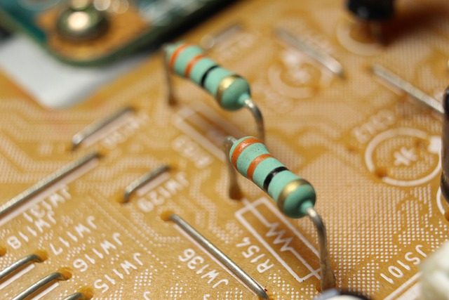
Resistors are one of the most common electrical components, and are used in virtually every device and circuit. They are generally composed of a conductive material that features an intermediate resistance; high enough to reduce current but low enough to still allow current to flow. Inside most resistors, you will find a conductive wire (of greater resistance than ordinary wire) wrapped around an insulating core.
Resistors allow us to customize the current and/or voltage to an entire circuit or part of a circuit. You can use them to build voltage dividers, which allows you to create multiple voltage ‘taps’ that are commonly used for reference voltages that can be used to troubleshoot a system, or simply to supply different voltages to other parts of the system.
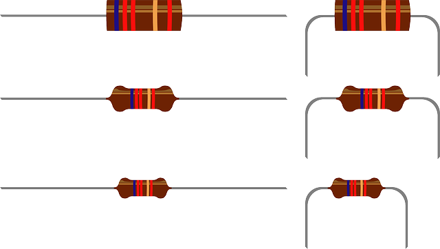
Resistors are either stamped/printed with their value of resistance, or feature colored lines that indicate the resistance value in Ohms. You can use a color code chart to figure out the resistance of a given resistor.
It is always a good idea to check the resistance by using a multimeter to measure it. Using a resistor whose value is too low could result in destroying other circuit components by allowing too much current to flow. Using a resistor whose value is too high can result in the circuit not functioning as intended.
Resistance in Wires
Like any conductors, wires always have some electrical resistance. This resistance can limit the current carrying capacity (called ampacity) of the wire; too high of a current can cause the wire to heat up too much.
In general, a thicker wire will increase the ampacity of the wire but will cost more. A copper wire also has a larger ampacity than an aluminum wire, because the resistivity of copper is lower than that of aluminum.
Wires come in standard sizes called gauges. A lower number gauge means a thicker wire; higher gauge wires are progressively thinner.
For most small electronics projects, 22-gauge wire is ideal. It is cheap, can handle the small amounts of current in most electronic circuits, and fits perfectly into electronic breadboards (little boards for circuit experimentation and prototyping).
Contact Resistance
Any time current must travel in between different materials, it encounters some resistance that adds to the system’s resistance as a whole. For instance, when you use a wire to connect two components in a circuit, the points of connection can never be perfectly conductive. The best case is a contact with extremely low resistance. However, the more contacts between components in series, the greater the overall effect of contact resistance.
Like many other ‘limitations’ in electronics, contact resistance is usually a small enough problem that it can either be ignored or incorporated into the design of a system.
We’ll learn more about resistors in Module 3, where we will explore resistors in series, parallel, combined with capacitors, and used to create voltage dividers.
Before that, we’ll need to develop a good understanding of Ohm’s Law, which combines voltage, current, and resistance.
Ohm’s Law is one of the most important mathematical relations in electronics and physics in general.
Let’s learn more in Lesson 6: Ohm’s Law.