Non-Inverting Op Amp
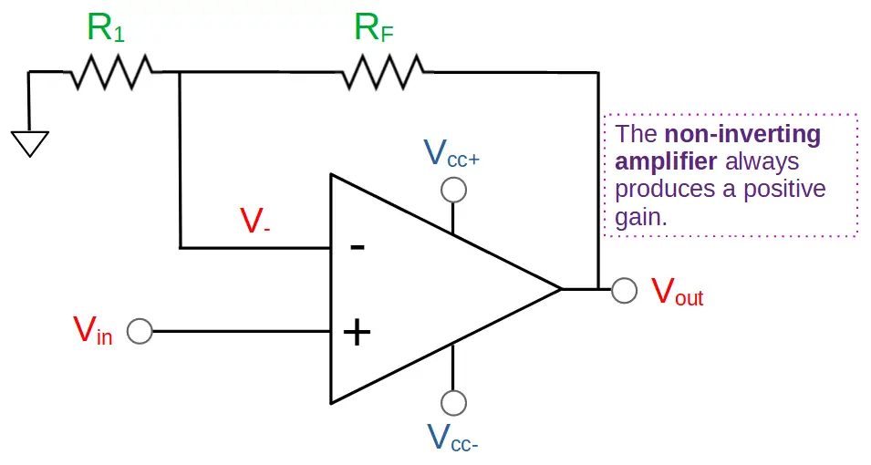
The non-inverting op amp is an amplifier that produces a positive gain with the same phase as the input. If the input signal is positive then the output of the non-inverting amp will also be positive.
The non-inverting amplifier uses an operational amplifier with a negative feedback loop between the output and the inverting input. It features two resistors that form a voltage divider. The gain of the amplifier is determined solely by the two resistors:
Gain = A_v = \frac{V_{out}}{V_{in}}=1+\frac{R_F}{R_1}This is an incredible feature of non-inverting op amps because it allows us to control the gain using only two external resistors.
Non-inverting op amps also feature the buffering capability of op amps. The high input impedance and low output impedance of the op amp allows the non-inverting amplifier to serve as a buffer during operation.
Non-inverting operational amplifiers are easy to understand and use. They rely on the fundamental functionality of op amps, which will be briefly reviewed below.
Introduction to the Non-Inverting Op Amp
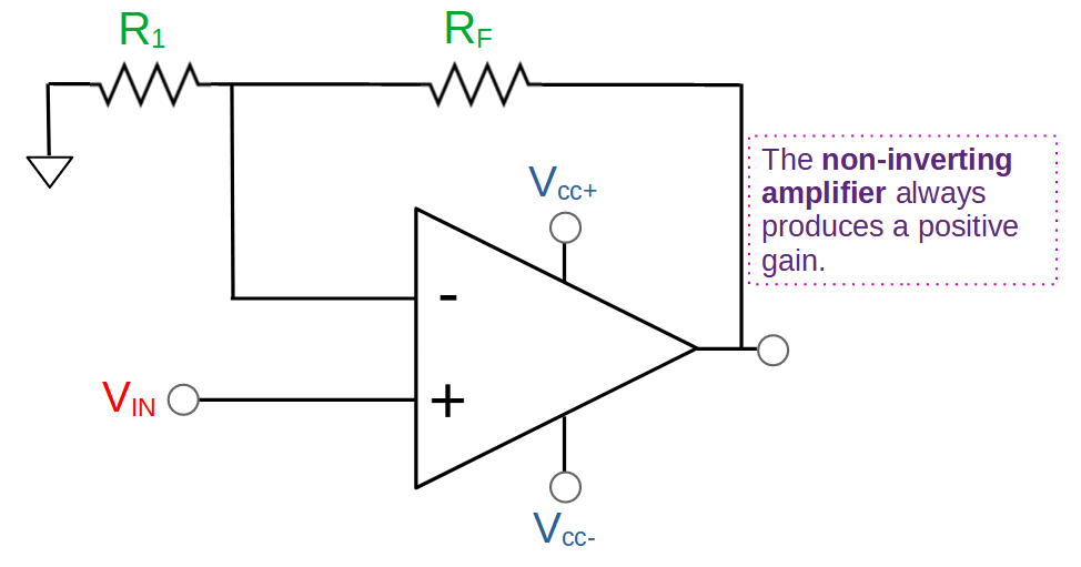
A non-inverting operational amplifier is a relatively simple circuit. The heart of the circuit is an op amp, which is typically an integrated circuit (IC). The 741 op amp is a popular example.
In order to create a non-inverting operational amplifier, we have to use the op amp in a specific configuration:
1. The input signal Vin goes to the non-inverting (+) input.
2. A feedback loop is used to connect the output with the inverting input (-) via feedback resistor RF.
3. An additional resistor, R1, connects the feedback loop and ground. The two resistors (RF and R1) form a voltage divider.
The operation of the voltage divider as well as the op amp are essential to the non-inverting amplifier. The gain is determined solely by the two resistors.
How Non-Inverting Op Amps Work
The non-inverting op amp circuit relies on the behavior of the op amp. However, the two resistors that form the voltage divider are also key to its’ operation.
In order to understand how non-inverting op amps work, we will need to review the basic operation of an operational amplifier. Then we will look at the voltage divider in the non-inverting amplifier and see how it works with the op amp.
By applying the voltage divider formula to the op amp configuration, we will easily be able to calculate the gain of the amplifier while gaining the intuitive knowledge of how the entire circuit works.
Op Amp Review
In order to see how the non-inverting amplifier works, we need to review the basic operation of an op amp.
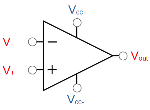
An op amp is a circuit with two inputs, and one output. It has very high input impedance and very low output impedance.
The inputs are:
- the non-inverting input (labelled with a positive sign ‘+‘), and
- the inverting input (labelled with a negative sign ‘–‘).
The op amp senses any difference in voltage between the two inputs. It drives the output either higher or lower if a voltage difference is detected between the inputs.
If the voltage on the non-inverting input is higher than the voltage on the inverting input, (i.e. V+ > V–) then the op amp will drive the output high.
If the voltage on the non-inverting input is lower than the voltage on the inverting input, (i.e. V+ < V–) then the op amp will drive the output low.
If the voltage is the same on both inputs, (i.e. V+ = V–) then the op amp output will be stable.
These three cases are illustrated below:
| Case | Non-Inverting Input | Inverting Input | Output |
| V+ > V– | Higher | Lower | HIGH |
| V+ < V– | Lower | Higher | LOW |
| V+ = V– | Equal | Equal | STABLE |
In other words, the op amp tries to drive its’ output high or low until the inputs are equal to each other. Saturation occurs if the op amp reaches either the upper or lower limits defined by the power supply levels.
Based on these characteristics, we can see that the op amp is designed to use negative feedback. This means that it is designed to be configured with its’ output connected with the inverting input (-).
The non-inverting amplifier is an example of this. It uses a negative feedback loop in combination with a voltage divider formed by two resistors.
Non-Inverting Op Amp Circuit
The simplest operational amplifier circuit that utilizes negative feedback is the voltage follower, also known as an op amp buffer. The buffer uses a wire to connect the output directly to the inverting input. It achieves a gain of one (1). Its name comes from the fact that it is surprisingly useful to buffer, or prevent interference, between stages of a complete system.
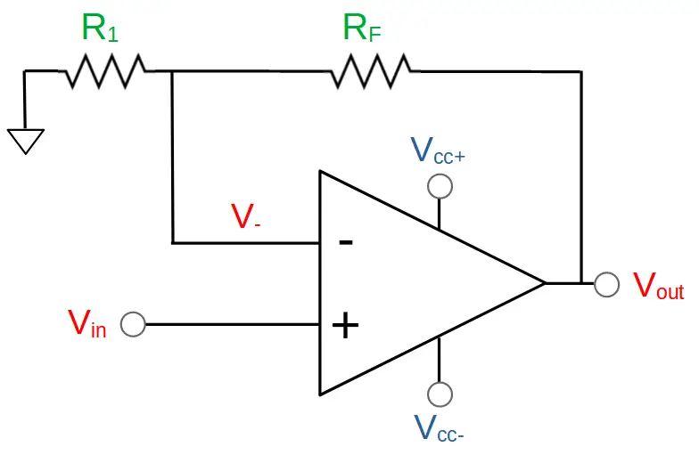
If we want to achieve a gain value greater than one, we need to create a non-inverting amplifier. We can simply add two resistors (R1 and RF) to the circuit:
The two resistors (R1 and RF) form a voltage divider:
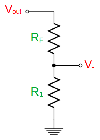
The relationship between Vout and V– can be determined by the voltage divider formula:
V_-=V_{out}\frac{R_1}{R_1+R_F}We can rearrange this to solve for the output Vout:
V_{out}=V_-\frac{R_1+R_F}{R_1}If the op amp’s output is stable, then the two inputs will be equal. In other words: V– = Vin
V_{out}=V_{in}\frac{R_1+R_F}{R_1}The amplifier’s gain is the ratio of the output to the input voltage:
Gain = A_v=\frac{V_{out}}{V_{in}}=\frac{R_1+R_F}{R_1}=1+\frac{R_F}{R_1}We can see three important facts about the gain:
- The gain can be controlled by changing the values of the two resistors alone. This means that we can create an amplifier with an arbitrarily large gain just by using two resistors.
- The gain is always greater than one.
- The gain can’t be negative. It will always be in phase with the input. This is where the term ‘non-inverting’ in non inverting op amp comes from.
Let’s see a few examples to gain an understanding of how this works.
Example 1: Non-Inverting Op Amp With Identical Resistors
Let’s take a simple case where the two resistors are identical to each other. We can use common 1K resistors:
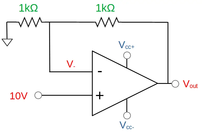
For this circuit, determine:
1. The gain of the amplifier Av.
2. The output Vout.
Solution for Example 1
The gain can be determined by the formula:
A_v=1+\frac{R_F}{R_1}=1+\frac{1k\Omega}{1k\Omega}=1+1=2The gain is equal to 2. This means that the output will be double the input:
V_{out}=A_vV_{in}=2V_{in}Given that Vin is 10V, we can easily calculate the output of the amplifier:
V_{out}=2V_{in}=2\times10V=20VExample 2: Non-Inverting Amp With Different Resistor
Now let’s see how changing the resistor values changes the gain and output of the circuit.
In this case, let’s double the value of resistor RF to 2kΩ:
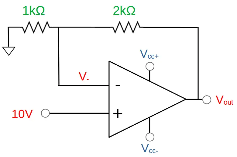
What will be the resulting gain Av and output Vout?
Solution for Example 2
Before do anything else, we can make an observation about this circuit. The 2kΩ resistor is twice the value of the 1kΩ resistor, and Vout needs to be dropped across both. This means that the 2kΩ resistor will drop 2/3 of Vout, and the 1kΩ resistor will drop the remaining 1/3 of Vout.
Now we can turn to the gain formula:
A_v=1+\frac{R_F}{R_1}=1+\frac{2k\Omega}{1k\Omega}=1+2=3With a gain value of 3, the output voltage will be three times that of the input:
V_{out}=A_v\times V_{in}=3\times 10V=30VWe were able to produce an amplifier with 3x gain just by changing a single resistor.
But what if the voltage goes too high? In this case, we might reach saturation.
Example 3: Non-Inverting Op Amp Saturation
For this example, we will use the same circuit as in Example 2, but this time we will supply the op amp with 25 V DC on the positive power supply terminal VCC+, and 0V (ground) on the negative terminal VCC-:
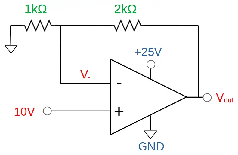
For this circuit, find the gain Av and output voltage Vout.
Solution to Example 3
The only thing that has changed is that we now have to work within the range supplied by the power supply.
The resistor values and input haven’t changed so the situation is much the same. The gain is still Av = 3:
A_v=1+\frac{R_F}{R_1}=1+\frac{2k\Omega}{1k\Omega}=1+2=3The output is still 30V:
V_{out}=A_v\times V_{in}=3\times 10V=30VOr is it?
The op amp wants to take the output to 30 V but the power supply is only providing 25V. This means that the output can only go as high as 25V and cannot go any higher.
This is called saturation. Since the op amp can’t raise the output any higher than 25V, the circuit will saturate at 25V.
Note: In actuality the op amp can’t supply the full 25V. The output will probably saturate about half a volt lower, at around 24.5V.
Non-Inverting Op Amp Applications
The non-inverting amplifier has several desirable characteristics that pair well with a variety of applications. These include:
- Positive gain that is greater than one (i.e. Av > 1).
- Output can be controlled by external resistors.
- Buffering quality of op amp due to high input impedance and low output impedance.
Amplification without phase inversion is a commonly desired characteristic, so the non-inverting op amp works well for many amplification requirements.
The other essential quality of non-inverting op amps is that they serve as a buffer between the stages of a circuit. This increases stability because it means that one stage is less likely to interfere with another.
High Gain Non-Inverting Op Amp
If we want to make an amplifier with extremely high gain, all we need to do is control the ratio of RF to R1. The larger this ratio is, the greater the gain of the amp will be.
This can be accomplished by using a higher-valued resistor for RF and a lower value resistor for R1.
At high gain values, we can ignore the ‘1’ in the gain formula:
A_v=1+\frac{R_F}{R_1}\rvert_{\frac{R_F}{R_1}\rightarrow\infin}\approx\frac{R_F}{R_1}In this case, we can assume that the gain is simply the ratio RF/R1.
So if we choose an RF of 1kΩ and R1 of 1Ω then the gain of the amplifier would be 1000. Larger values can easily be achieved by further increasing RF or decreasing R1.
Non Inverting Op Amp – Conclusion
The non-inverting op amp is an essential op amp circuit.
It uses an operational amplifier combined with two resistors that are used as a voltage divider. The output of the voltage divider is fed into the inverting input to produce a negative feedback loop.
This configuration allows for the control of the amplifier gain using the two resistors. The gain will always be the same phase as the input; it does not invert the signal. In addition, the gain is always greater than one.
This means that the output must always be greater than the input.