Notch Filter
A notch filter is a type of band stop filter that is designed to attenuate a very small band of frequencies.
Both band stop filters and notch filters are designed to selectively remove designated frequencies from a signal. Whereas band stop filters can be designed to stop a large band of frequencies, notch filters are often designed to remove just a very narrow band of frequencies and those very close to it.
Like other types of filter circuits, notch filters are designed to remove part of complex AC signal.
The term notch filter is also used a synonym for band stop filters, and some manufacturers don’t distinguish between them.
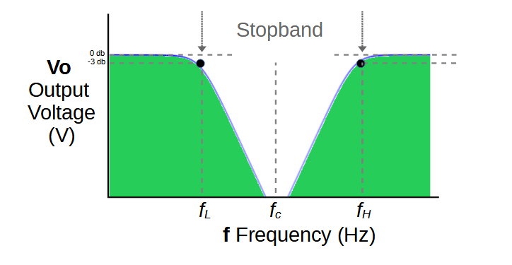
One of the main practical differences between band stop filters and notch filters is that band stop filters tend to be defined by two frequencies: fL, which defines the low cut-off frequency, and fH which defines the high cut-off frequency. These two frequencies are used to design the circuit.
In contrast, notch filters are most often defined by the center frequency fc. The center frequency is the frequency in the middle of the notch, that is, the frequency that experiences the greatest attenuation.
Notch vs. Band Stop Filters
Every notch filter is a band stop filter, and they are often referred to as synonyms for one another.
When they are distinguished from each other, the notch filter is usually designed to remove a single frequency or an extremely tight band of frequencies.
In contrast, a band stop filter may be used to eliminate a wider band of frequencies. One example is an FM trap, which blocks a wide band of frequencies associated with FM signals.
There can be advantages and drawbacks to both band stop and notch filters. Since notch filters are designed to eliminate a single target frequency, they may need to be tuned by different users, even the systems are almost identical. If the frequency that needs to be attenuated is just a bit off from the frequency of the notch filter, the filter may not perform as well as required. Many notch filters are tunable for this reason.
On the other hand, a band stop filter may attenuate a wider range of frequencies than desired, resulting in poor signal quality or lost information.
Notch Filter Circuit
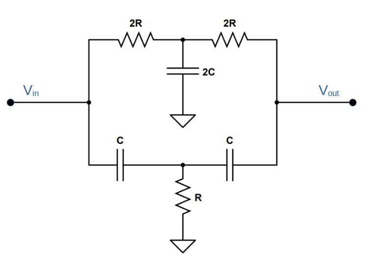
There are a variety of notch filters that vary in design and functionality. One of the most common types of notch filter is the Twin-T Notch Filter.
The twin-t notch filter is very similar to the circuit we saw in our lesson on band stop filters. It features a high pass filter in parallel with a low pass filter, with an additional resistor and capacitor used to further reduce the size of the stop band.
Note that the relative values of resistance and capacitance are defined in the notch filter. The resistors labelled ‘2R’ have twice the resistance of the resistor labelled ‘R‘, and the capacitor labelled ‘2C‘ must be double the capacitance of the two capacitors labelled ‘C‘.
With these values, the center frequency of the filter will be:
f_c = \frac{1}{4\pi RC}Twin-T Notch Filter Circuit Diagram
How Notch Filters Work
Notch filters are a type of band stop filter, and operate using the same principles. Notch filters have a center frequency which is the frequency that is the most attenuated. In other words, the center frequency is in the middle of the stop band. In the case of single-frequency notch filters, the center frequency will be the designated frequency of the filter itself.
Two filters are used in parallel in order to produce the desired output:
A low pass filter is used to generate the output below the center frequency. The characteristics (resistance and capacitance) determines its’ properties including the low-frequency cut-off fL.
A high pass filter is used to generate the output above the center frequency. It’s cut-off frequency, fH, is also determined by the values of the resistor and capacitor used.
The output from both filter circuits are then combined to form the notch filter output. In general, fH is chosen to be slightly greater than fL. The difference between fH and fL is the stopband gap. A notch filter that attenuates 1 MHz, for instance, will feature a high cut-off frequency that is 1 MHz greater than the low cut-off frequency.
Because notch filters ideally will sharply attenuate only a small frequency band, they tend to use more complex designs that allow them reduce the band and steepen the slope at the edges of the stopband. For example, the Twin-T notch filter use slightly more complex low and high pass filters to achieve this.