L-Pad Attenuator
An L-pad attenuator, also called an L-pad, is a circuit with two impedances; one in series and one in parallel with the load.
Due to this series/parallel configuration, the circuit resembles the shape of the letter L. The ‘pad’ designation in the name is due to the effect of attenuating, or ‘padding down’ the signal, a term used in acoustics.
L-pad attenuators are frequently used to perform impedance matching, which is used to increase power transfer and minimize reflection in transmission lines.
L-pads are typically constructed of two linked potentiometers (also called rheostats). As the impedance of one is increased, the impedance of the other is decreased and vice-versa. This maintains a constant total impedance in one direction. A slightly more complex attenuator called a T-pad can be used to maintain constant total impedance in both directions.
Since L-pads are constructed of two resistive elements, they can be thought of as an implementation of a specific type of voltage divider (i.e. a voltage divider with coupled potentiometers).
Impedance Matching
In order to understand how L-pads work and why they are used, it is important to understand the concept of impedance matching.
Impedance is the resistance to the flow of electric current in a circuit. In DC circuits, impedance is the same as resistance. In AC circuits, impedance is also contributed by capacitance and inductance (in addition to resistance). Inductors and capacitors don’t dissipate power like resistors, but they do restrict current (like resistors) in AC circuits.
What is Impedance Matching?
Impedance matching is a technique used to maximize power transfer in a circuit. It turns out that maximizing power transfer requires that the source and load impedances be matched to each other. This result comes from the maximum power transfer theorem, which will be briefly discussed in the next section (just below).
Before we discuss the maximum power transfer theorem, it is helpful to understand that impedance matching is not used in every situation. The primary objective of impedance matching is to maximize the power that is transferred between the source and load.
As it normally involves introducing additional impedance to a circuit (as is the case when using an L-pad attenuator), impedance matching actually decreases the efficiency of the circuit. However, it also prevents signal reflections and standing waves in transmission lines and is therefore desirable in a wide variety of situations.
Maximum Power Transfer Theorem
The maximum power transfer theorem states that maximum power is transferred from the source to the load when the impedance of one matches the complex conjugate of the other.
In a purely resistive circuit, this means that the resistance of the source must equal the resistance of the load. For circuits with capacitive or inductive properties, the impedances of the capacitors and inductors in the load must be the opposite of the impedances of the capacitors and inductors in the source.
Impedance Matching With L-Pad Attenuator
As long as the source and load impedances are primarily resistive, then an L-pad consisting of resistors can be used to match the source and load impedances. If the source or load impedance includes capacitive or inductive elements, then an L configuration of capacitor and inductor can be used to match the complex part of the impedance.
When using an L-pad to perform impedance matching, the Z1 side of the L-pad always faces the side (either source or load) with higher impedance.
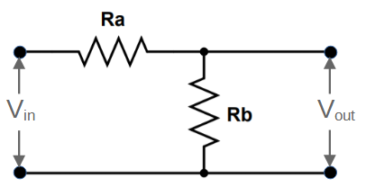
With this configuration, the values of the resistors Ra and Rb can be determined by using the following formulas:
R_b=\frac{Z_2}{\sqrt{1-\frac{Z_2}{Z_1}}}R_a=\frac{Z_1Z_2}{R_b}L-Pad Attenuator Circuit
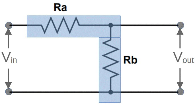
A basic L-pad attenuator is essentially identical to a voltage divider circuit. In both cases, there are two resistive elements in series with each other. An output is taken from between the two resistive elements, and the voltage is measured between this point and ground.
We can use the voltage divider formula to determine the output voltage of the L-pad given the input voltage and resistance values:
V_{out} = V_{in} \frac{R_2}{R_1+R_2}Voltage Divider vs. L-Pad Attenuator
In terms of design, the L-pad attenuator has some restrictions that a voltage divider does not have:
- The L-pad must use potentiometers (rheostats) rather than standard resistors.
- The resistance values of the two potentiometers must be linked so that the total impedance remains the same. When one resistance is increased, the other is decreased and vice versa.