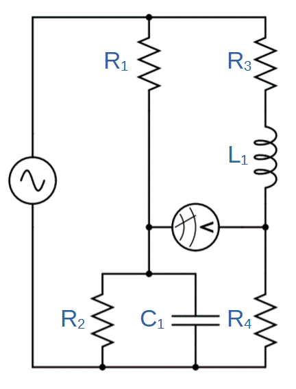
Maxwell Bridge

The Maxwell bridge is an electric circuit that is uses a bridge topology to determine an unknown value of inductance.
Based on the Wheatstone bridge, the Maxwell bridge extends the concept of balance in a bridge circuit.
In fact, the Maxwell bridge operates very similarly to the Wheatstone bridge. The primary difference is that the Maxwell bridge is designed to determine an unknown inductance while the Wheatstone bridge is used to determine an unknown resistance.
Just like the Wheatstone bridge, the Maxwell bridge is used by constructing the circuit and then adjusting it until zero current flows through the meter (i.e. ‘balancing’ the circuit).
The unknown inductance can be determined from equations that must be true while the circuit is balanced. These results are derived later in this article:
L_1=R_1R_4C_1
R_3=\frac{R_1R_4}{R_2}Table of Bridge Circuits
The following table shows a comparison of important bridge circuits used for measuring unknown quantities of resistance, capacitance, inductance, or frequency:
| Bridge Circuit Type | Type of Measurement | Equation (while balanced) |
| Wheatstone Bridge | Resistance | R4 = (R2R3)/R1 |
| Wien Bridge | Capacitance or Frequency | C4/C2 = R4/R3 – R2/R1, ω2 = 1/(C1C2R1R2) |
| Maxwell Bridge | Inductance | L1 = R1R4C1 |
Maxwell Bridge Circuit Diagram

The Maxwell bridge circuit consists of two primary parallel branches that are bridged by a voltmeter or ammeter.
In general, this circuit is very similar to the Wheatstone bridge, with two exceptions: 1) the first branch has a capacitor C1 in parallel with resistor R2, and 2) we are measuring the inductance of L1. Resistor R2 is typically a potentiometer that can be adjusted to help achieve a balanced circuit.
Balanced Maxwell Bridge Circuit
Like other bridge circuits, the Maxwell bridge is used by balancing the circuit. Balancing the circuit requires tweaking values of resistance or capacitance until there is zero potential difference across the meter.
The meter in the circuit can be either a voltmeter or an ammeter. If an ammeter is used, the circuit is balanced when no current flows through the meter, which is equivalent to a voltmeter measuring zero volts. This is also known as a ‘null’ measurement.
In order for this to be true, the ratio of the impedances between branches must be equal. This is identical to the balancing conditions in the Wheatstone and Wien bridge circuits.
We can start by setting up the general balancing equations, just as we did in our lessons on the Wheatstone bridge and Wien bridge:
\frac{Z_1}{Z_2}=\frac{Z_3}{Z_4}Note that each value is the total impedance for that branch. The first branch (branch ‘1’ ) has an impedance of Z1 and contains resistor R1, so Z1 = R1. The fourth branch is similar; Z4 = R4. But the second and third branches are different: Z2 must take into account R2 as well as C1, and Z3 must include R3 and L1.
We can already simplify our relation by substituting R1 and R4 for Z1 and Z4:
\frac{R_1}{Z_2}=\frac{Z_3}{R_4}In order to calculate the values of impedances Z2 and Z3, we have to include the values of capacitor C1 and inductor C1:
Z_2=\frac{1}{\frac{1}{R_2}+\frac{1}{jX_{C1}}}Just as we saw with the Wien bridge, we can plug in the value of XC1 and simplify:
Z_2=[\frac{1}{R_2}+\frac{1}{j(\frac{1}{\omega C_1})}]^{-1}=[\frac{1}{R_2}+j\omega C_1]^{-1}=\frac{R_2}{1+j\omega R_2C_1}Let’s calculate the value of Z3:
Z_3=R_3+Z_{L1}=R_3+j\omega L_1Now we can set up the equations for the Maxwell bridge under balanced conditions.
Balancing the Maxwell Bridge
Now let’s combine these results with the conditions for a balanced circuit:
\frac{R_1}{Z_2}=\frac{Z_3}{R_4} => R_1R_4=Z_2Z_3To go further, we’ll need to calculate Z2Z3:
Z_2Z_3= [\frac{R_2}{1+j\omega R_2C_1}][R_3+j\omega L_1]Setting R1R4 equal to Z2Z3 (per the balancing conditions):
R_1R_4=[\frac{R_2}{1+j\omega R_2C_1}][R_3+j\omega L_1]We can simplify:
R_1R_4(1+j\omega R_2C_1)=R_2R_3+j\omega R_2L_1
R_1R_4+j\omega R_1R_2R_4C_1 = R_2R_3+j\omega R_2L_1
If we set the real and imaginary parts of the right and left sides equal, we obtain two equations:
R_1R_4=R_2R_3
j\omega R_1R_2R_4C_1 = j\omega R_2L_1
We can then solve for both an unknown resistance and an unknown inductance:
R_1=\frac{R_2R_3}{R_4}L_1=R_1R_4C_1