Wien Bridge
The Wien bridge is a circuit that uses a bridge topology to accurately measure capacitance or frequency.
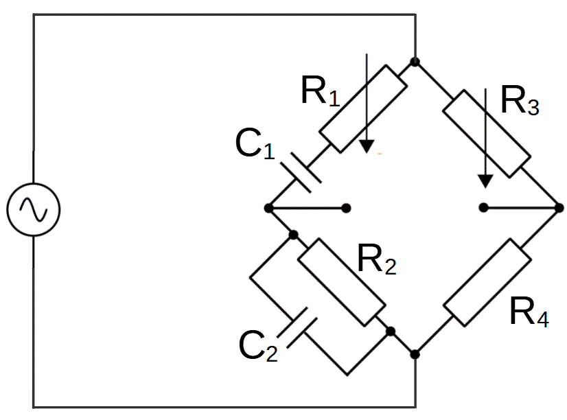
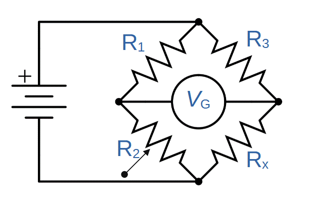
In terms of construction, the Wien bridge is very similar to the Wheatstone bridge, with the addition of one capacitor in series and another in parallel. Both use the concept of balancing a bridge circuit to perform a measurement.

The basic Wien bridge has one capacitor (C1) in series with resistor R1 and one capacitor (C2) in parallel with resistor R2.
Balanced Wien Bridge Circuit
In order to understand the functionality of the Wien bridge, we have to look at how the circuit is balanced.
Recall that the Wheatstone bridge circuit balances when the ratio of the resistances of the first and second arms (R1/R2) is equal to the ratio of the third and fourth arms (R2/R3):

\frac{R_1}{R_2}=\frac{R_3}{R_4}\,(Wheatstone\,Bridge)The Wien bridge circuit extends this by adding two capacitors. Balancing the circuit now requires including the impedance introduced by the capacitors (i.e. capacitive reactance).
The balancing condition can be found by trading the branch resistances of the Wheatstone bridge, for the total impedances of the new Wien bridge circuit:
\frac{Z_1}{Z_2}=\frac{Z_3}{Z_4}\,(Wien\,Bridge)Like the Wheatstone bridge, the Wien bridge circuit is balanced when the ratio of the impedances of the first and second arms (Z1/Z2) is equal to the ratio of the impedances of the third and fourth arms (Z3/Z4). The primary difference is that impedance only includes resistance in the Wheatstone bridge circuit.
Let’s solve for each value of impedance in the Wien Bridge circuit.
Impedance of Arm 1
The impedance of the first arm (Z1) is determined by resistor R1 and the capacitive reactance XC1 of C1. The two terms add, with the reactance being differentiated by the inclusion of the unit imaginary number j (which is equal to the square root of negative one).
Z_1=R_1-jX_{C1}=R_1-\frac{j}{\omega C_1}Impedance of Arm 2
The impedance of the second arm, like the first, depends on the contributions of both the resistor and capacitor.
This time, however, the capacitor is in parallel with the resistor. This means that we have to use the equation for parallel impedances in order to find Z2.
Z_2=\frac{1}{\frac{1}{R_2}+\frac{1}{jX_{C2}}}We can plug in the value of XC2 and simplify:
Z_2=[\frac{1}{R_2}+\frac{1}{j(\frac{1}{\omega C_2})}]^{-1}=[\frac{1}{R_2}+j\omega C_2]^{-1}Impedances of Arms 3 and 4
The impedances of arms 3 and 4 are equal to the value of the corresponding resistors:
Z_3=R_3
Z_4=R_4
Balancing the Wien Bridge
Now let’s combine these results with the conditions for a balanced circuit:
\frac{Z_1}{Z_2}=\frac{Z_3}{Z_4} => Z_1Z_4=Z_2Z_3To go further, we’ll need to calculate Z1Z4 and Z2Z3:
Z_1Z_4=(R_1-\frac{j}{\omega C})R_4Z_2Z_3=[\frac{1}{R_2}+j\omega C_2]^{-1}R_3=\frac{R_3}{\frac{1}{R_2}+j\omega C_2}Setting Z1Z4 equal to Z2Z3 (per the balancing conditions):
(R_1-\frac{j}{\omega C})R_4=\frac{R_3}{\frac{1}{R_2}+j\omega C_2}\omega ^2=\frac{1}{C_1C_2R_1R_2}\frac{C_4}{C_2}=\frac{R_4}{R_3}-\frac{R_2}{R_1}