Introduction to Electric Current
Electric current is one of the most important concepts in electrical circuits.
Electric current is rate of flow of electric charge. Current is measured in units of amperes, which are usually called ‘amps’. One amp is a lot of current. It is equal to one coulomb per second, or about 6 x 10¹⁸ electrons per second.
Electric current is defined as the the direction of flow of positive charge and therefore is always in the opposite direction to electron flow.
The two most common types of electric current are direct current (DC) and alternating current (AC). In both cases, current describes the movement of electrons. Direct current uses a steady-state current that always moves in the same direction. Alternating current features a current that changes in amplitude and direction over time.
- What is Electric Current?
- Direction of Electric Current
- Current is an Abstract Measure of Charge Flow
- What is the SI Unit for Electric Current?
- How is Electric Current Measured?
- Electric Current in Series and Parallel Circuits
- Electric Current in DC and AC Systems
- Advanced Topic: Electric Current in Dynamic Systems
Current is the flow of charge through an electric network. Current describes the flow of electricity through a system and allows us to measure that flow. A basic understanding of current is the first real step toward understanding how circuits and devices work.
In a previous lesson, we learned about electric charge. We now turn to the question ‘What happens when we give charge a little push and make it move through a conductor or a circuit?’ The answer is electric current.
What is Electric Current?
Electric current is the rate of the flow of electric charge through a point or cross-section of a wire or device in an electric circuit.
Electric current is defined in units of electric charge per unit time, so it builds on the concept of electric charge, which we’ve already explored. Current is usually abbreviated with the letter ‘I’. Electric charge is normally abbreviated as ‘q’ (sometimes uppercase ‘Q’), and time is abbreviated by the letter ‘t’. So current is defined as:
Current (I) = \frac{Charge (q)}{Time (t)} =>I = \frac{q}{t}In our previous lesson on electric charge, we saw that the unit of charge, the Coulomb, is based on a fundamental physical concept, which is the charge of a single electron, or e = 1.6 x 10⁻¹⁹ Coulomb.
A Coulomb is therefore grounded in something that exists fundamentally in nature. The charge of the electron and proton is a fundamental property of matter, without which atoms would not exist.
Electrons and protons both have an electric charge; the charge of the proton is of equal strength but opposite ‘sign’ to the charge of the electron. The electric charge is what causes electrons to repel each other and to attract/be attracted by protons. This attraction and repulsion occurs because an electric field surrounds every charged particle, and exerts a Coulomb force on other charged particles.
Electric current is what you get when you take electric charge and move it somewhere.
We have also learned that when we want to use electricity to do something useful, we need to provide energy to electrons so that they will move through an electric circuit. Electric circuits gets this energy from a power source. A power source (usually a generator or battery) is what causes charge to flow through the circuit, creating electric current.
Direction of Electric Current
The concept of electric current was developed in part by Benjamin Franklin, who named the ‘positive’ direction of current based on the way that he believed electricity was flowing.
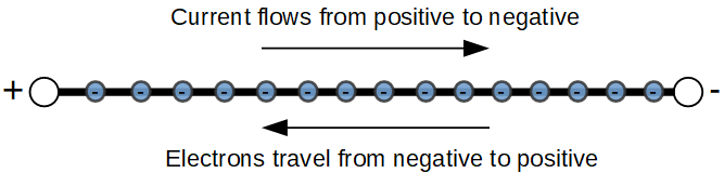
Somewhat unfortunately, the direction of electron movement is actually opposite the direction of electron flow. We say that current flows from an area of positive (+) potential to negative (-) potential. However in reality, the electrons are flowing from negative (-) potential to positive (+) potential.
The sign of electric current is based on how a positively charged particle would move through a circuit. Since electrons are negatively charged, their movement is always opposite the direction of current flow.
You can think about positive and negative potential as the two sides (terminals) of a battery. The positive terminal of the battery, called the anode, is at a higher electric potential than the negative terminal. This is akin to having more potential energy. In the same way that water flows downhill due to the higher potential of the hill relative to the valley, current flows from points of higher to lower potential.
We’ll see the concept of electric potential explored in much greater detail in the next lesson, on voltage. For now, just remember that current flows from the positive to the negative potential, opposite to the movement of electrons.
For example, in a circuit powered by a battery, electrons flow from the negative terminal to the positive terminal. The negative terminal is so designated because it is the source of negatively charged particles (electrons).
At the same time, current starts at the positive terminal of the voltage source, on the left side of the circuit. The current then travels in a clockwise direction through resistor R1, and re-enters the battery at the negative terminal.
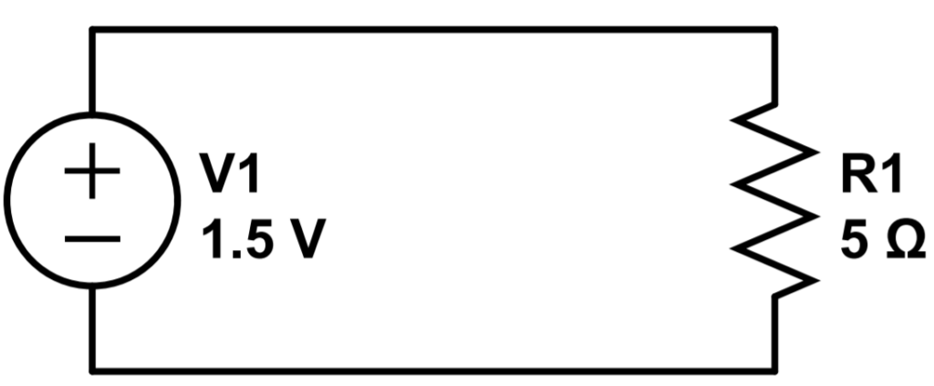
What we define as current, as mentioned, is opposite the electron flow. Electrons start at the negative terminal of the battery, move counter-clockwise through the circuit, through the resistor R1, and re-enter the battery at the positive terminal. This is what is physically happening in the circuit. However since electrons have a negative charge, we define the current as moving in the opposite direction.
Current is an Abstract Measure of Charge Flow
As we can see, the concept of current is abstract. It is a theoretical measurement of the movement of positive charge carriers, even when the system only contains negative charge carriers.
Luckily, the fact that current doesn’t correspond with the direction of charge carrier flow is not a significant factor in understanding or analyzing circuits. It just means that we have to keep directionality in mind.
One thing to keep in mind is that, with simple circuits, we don’t really need to know what the electrons are doing; we can simply use an abstract description of ‘current flow’. However in electronic devices such as vacuum tubes, diodes, and transistors, it is important to know what the electrons are doing; these devices wouldn’t make sense without the specific properties of electrons.
For that reason, in this course we try to use a dual-approach in which both current and electron flow are described when needed.
What is the SI Unit for Electric Current?
The SI unit for current is the ampere, which is defined as 1 Coulomb per 1 second. The unit ampere is abbreviated by ‘amp’ or uppercase ‘A’.
1 \hspace{1mm} amp = \frac{1 \hspace{1mm} coulomb}{second} = 1A = \frac{1 C}{s}As we saw previously, we don’t use the SI unit abbreviations to display formulas, because formulas are meant to be used with any units; you can always convert to SI units by adjusting your results based on the units you started with.
You might notice that this formula is just the SI version of the general formula for electric current that we saw earlier:
I = \frac{q}{t}Which should be read as ‘current equals charge divided by time’. In other words, the amount of charge that passes through any point in a circuit, per unit time, is the electric current.
If we were to measure, one electron at a time, the amount of electrons that pass through a wire, using a stop watch, we could add up the charge (in Coulombs) and divide by the observation time on the stopwatch (in seconds), to determine the current.
How is Electric Current Measured?
In reality, a device called an ammeter is normally used to measure the current passing through part of a circuit. The most common type of ammeter is inserted in series with the circuit. Here is a simple circuit consisting of a DC voltage source and a resistor. If we wanted to measure the current using an ammeter in series, we would simply connect the ammeter to the circuit like this:
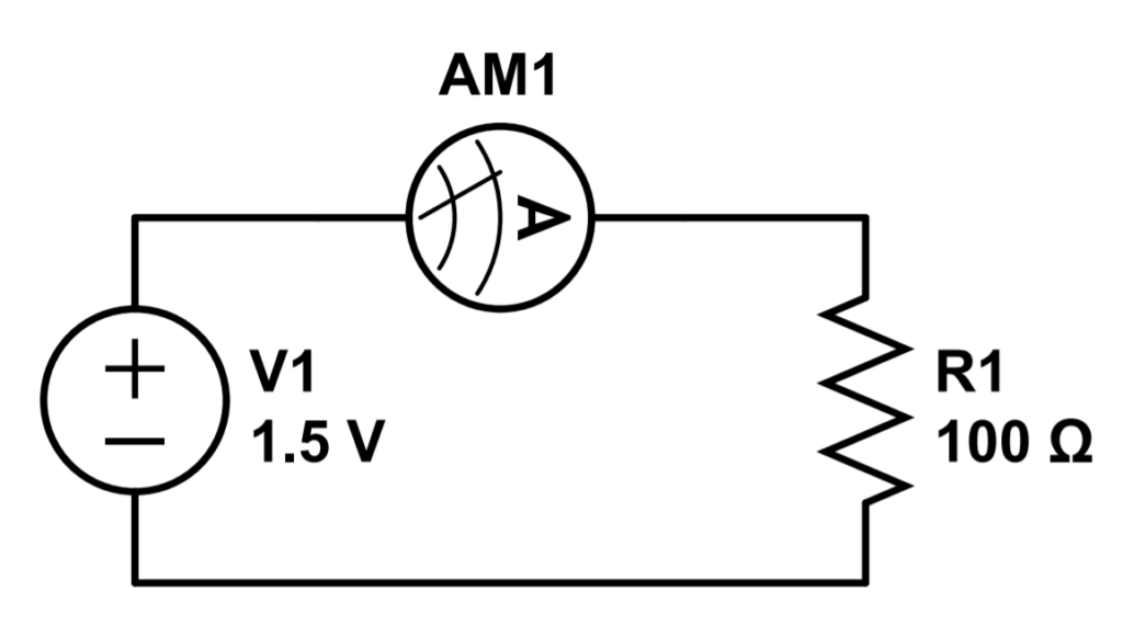
This circuit is called a series circuit because there is only one path for electric current to flow through. In this case, it doesn’t matter where we place the ammeter in the circuit. In this circuit, the current is dictated by the single resistor so we would obtain the same result by placing the ammeter before or after the resistor.
The only downside to this type of ammeter is that you must de-energize the circuit and insert the ammeter. Another common ammeter used for troubleshooting is the clamp ammeter, which enables you to obtain a reading of the current without requiring the circuit to be modified. You can simply open and close the clamp around the circuit whose current you are trying to measure.
Electric Current in Series and Parallel Circuits
Electric circuits can be constructed by placing components in series, in parallel, or in a combination of the two. These configurations are defined by the way electric current flows through the circuit:
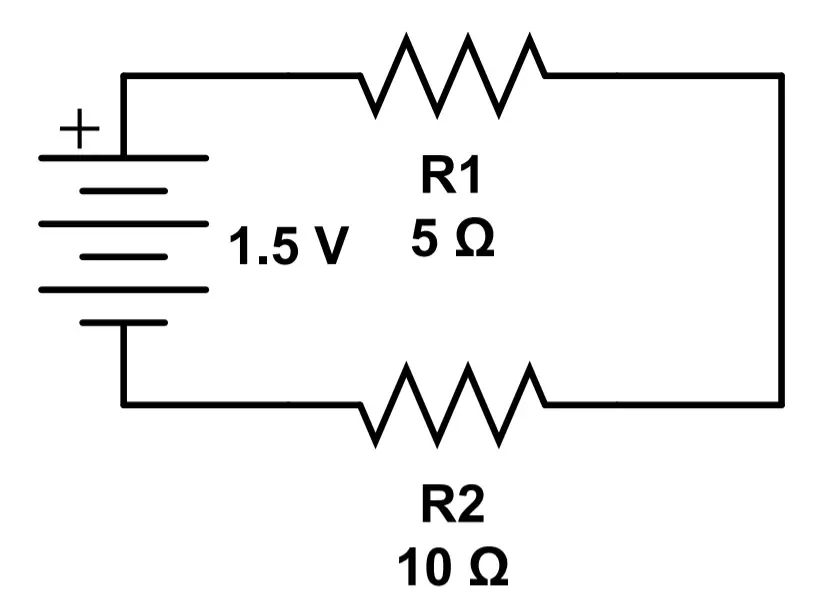
Series circuits have only one path for current to follow. They consist of a single ‘loop’, or conductive path, around which all current will flow. The current in a series circuit is the same at all points in the circuit.
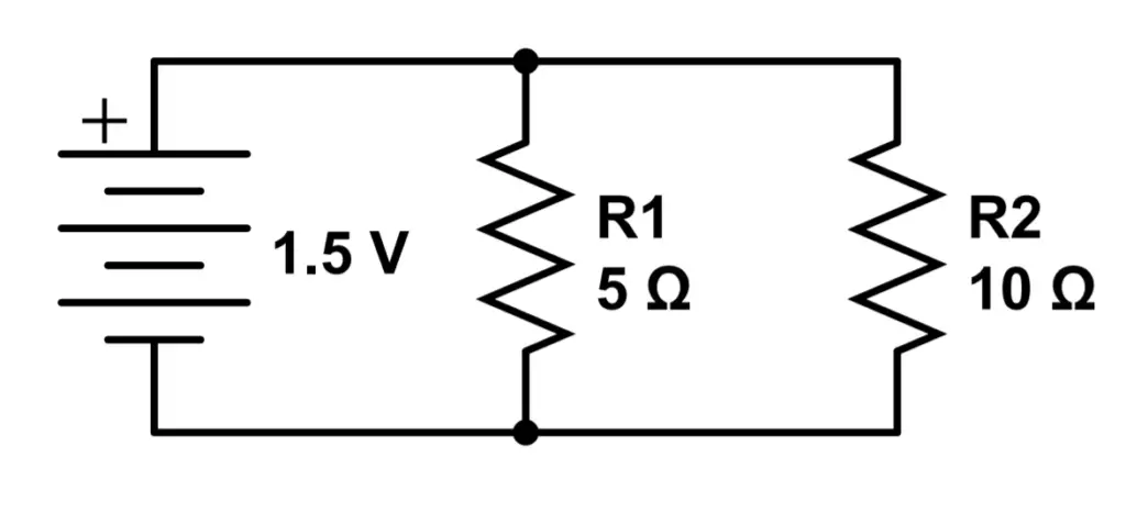
Parallel circuits have multiple paths for current to follow. They consist of multiple ‘loops’, or conductive paths, around which current can flow. The current in a parallel circuit may be different in each current path, or ‘branch’.
Electric Current in DC and AC Systems
There are two types of electric current that we find all over the place:
Direct current (DC) systems use an electric current that is constant over time. In other words, the current does not change. It always moves in the same direction and always has the same magnitude. In a DC circuit, electrons always move in the same direction, at the same speed. DC circuits can be found in many electronic devices. Basically everything powered by batteries use DC, including laptops and cell phones. The main disadvantage to direct current (DC) systems is that only a changing current allows us to use a device called a transformer. In other words, you can’t use a transformer with DC. Transformers are really useful for increasing or decreasing electric current (and voltage), which is why alternating current (AC) systems are popular.
Alternating Current (AC) systems use an electric current that changes in time. The current in an AC system looks like a (sine) wave. It increases to a peak, then decreases back down. It decreases to zero and then it actually goes in the other direction. In an AC circuit, electrons move one way through the circuit, and then back in the opposite direction. The electrons still move opposite to the direction of the electric current. AC circuits can use transformers, which enable us to easily control voltage and current. Transformers are the reason that when you plug a device into a wall outlet, you are tapping into AC power. Anything powered by an electric grid or mains electricity, is generally using AC power.
Advanced Topic: Electric Current in Dynamic Systems
Steady State Current
Let’s get back to our original formula of
I = \frac{q}{t}This formula is a great way to understand current, but it isn’t exactly true in all cases. It is true if the system is in a steady state, but if the rate of charge flow changes in time, then we have to use some basic calculus. Systems that are not steady state can be referred to as dynamic.
In general, charge can be expressed as a function of time q(t). If you haven’t learned about functions yet, they are basically equations that are based on variables.
The expression ‘q(t)’ should be read as ‘q of t’, or ‘q as a function of time’, where ‘q’ denotes charge and ‘t’ denotes time.
In a steady state DC system, charge (q) will always be a linear function of time (t). Let’s say that 5 Coulombs are passing through a wire per second. The equation for q will read:
q(t) = 5t
If this is true, then the above formula will work! We’ll see why this is true in a moment.
Dynamic Current
If however, the system is dynamic, then charge (q) may be a more complex function of time. It might have a quadratic relation, meaning that a term is squared, like:
q(t) = t^2 + 5t
In this case, the relation of I = q/t is no longer true because the relationship between charge movement and time is not linear.
The complete relationship between current and charge is that current is the time derivative of charge, also called the derivative of charge with respect to time:
Simplified\, formula: I = \frac{q}{t} \\ ...\\
Complete\, formula: I = \frac{dq}{dt}
In the steady state example of q(t) = 5t, the simplified formula works because the derivative of q(t) is 5, which is the same result we would obtain if we simply divided the charge by the unit seconds:
Simplified\, formula: I = \frac{5\, Coulomb}{1\, second} = 5\, Amps\\
...\\
Complete formula: I = \frac{dq}{dt} = \frac{d}{dt}(5t)= 5\, Amps
In the more complex case, we must take the derivative of q, and we find that because the charge is not steady state, the current is not steady state either (by the definition of current). In other words, if the amount of charge flowing changes in time, current changes with it.
Let’s return to the example of q(t) = t^2 + 5t; in this case, we need to find the derivative with respect to time:
I = \frac{d}{dt}(t^2+5t)=2t+5In this case, the current increases linearly with time. This type of example is not common; a more common example might be a function that as quadratic before reaching steady state when first starting a circuit.
The most common example of a dynamic current is that of alternating current (AC), in which the current is described by a sine wave.
Now that we have a solid understand of electric current, let’s explore the topic of voltage in detail in Lesson 4: Voltage.