Zener Diode
A Zener diode is a diode that allows current to pass when a sufficiently large negative bias is applied.
The Zener diode is designed to be reverse biased.
Like other diodes, Zener diodes conduct when a forward bias is applied. However, they also allow current to pass when a large negative bias is applied. This is called the Zener Voltage.
Zener diodes are one of the most interesting types of diodes, in terms of both how they work and how they are used.
Introduction to the Zener Diode
What Are Zener Diodes?
Zener diodes are a special type of diode. Like other diodes, they are essentially P-N junctions and allow current to flow while they are forward biased. However, unlike other diodes, they are also designed to allow current to flow when negatively biased.
You may recall that regular diodes also allow current to flow when a large enough reverse bias, called the breakdown voltage (VB), is applied. There are two major differences between regular diodes and Zener diodes:
First, the Zener voltage (VZ) of a Zener diode is much smaller than the breakdown voltage (VB) of a conventional diode. Zener Voltages (VZ) of around -2.5V are common, whereas conventional diodes often have a breakdown voltage (VB) of -50V to -100V. Just as importantly, Zener diodes with hundreds of values of VZ are commonly available, making them easy to design a circuit with.
Second, Zener diodes are designed to withstand the negative bias without damage to the diode itself, and are engineered specifically for that purpose.
As a result, Zener diodes are typically used in reverse bias mode.
The Zener Effect
Zener diodes are named after physicist Clarence Zener, who was the first scientist to accurately explain the electrical breakdown of insulators.
The characteristic Zener voltage of a Zener diode is possible due to a phenomenon called the Zener Effect. The Zener Effect relies on quantum mechanics to work. When the P-N junction of a diode is made narrow enough, a negative bias produces a large depletion region. There is a resulting electric field across the depletion region. A negative bias larger than VZ will then allow electrons to tunnel across the depletion region, resulting in a high current through the diode.
Identifying the Anode and Cathode of a Zener Diode

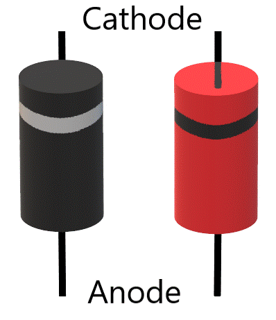
The directionality of a Zener diode is typically marked with a ring designating the cathode. For colored Zener diodes (often red), the cathode ring is typically black. For black Zener diodes, the cathode ring is typically grey. You can also double check the directionality using a multimeter, as described in the section below on testing/troubleshooting Zener Diodes.
While standard diodes are most often used in the forward biased configuration, Zener diodes are designed to be used while reverse-biased. This means that the cathode of the Zener diode will be on the positive (+) side of the circuit, while the anode will be on the negative (-) side.
Zener Diode vs. Diode
Zener diodes are a type of diode; just like other diodes, they are based on P-N junctions.
However, most diodes are designed to function like a one-way or check valve in the circuit. In other words, most diodes work by only allowing current to flow in one direction. Regular diodes are used in circuits with a forward bias applied, meaning that a positive voltage is placed across the diode, with current being driven from the anode (the ‘p-side’ of the junction), to the cathode (the ‘n-side’ of the junction).
Zener diodes are actually designed to be used in the opposite orientation (with a negative bias applied). Like other diodes, they still allow current to flow with a forward bias. Zener diodes are usually placed in a circuit in a reverse bias position. They have a characteristic voltage called the Zener Voltage (VZ). If a reverse bias is applied that exceeds the Zener Voltage, a Zener diode will allow current to flow in the reverse direction.
The difference between standard diodes and Zener diodes are primarily due to construction differences. Compared with regular diodes, Zener diodes are doped to much higher levels and have a narrower P-N junction.
How Are Zener Diodes Used?
Zener diodes have two properties that have proven to be incredibly useful in many circuits.
First, Zener diodes only allow current to flow when a high enough voltage is placed across it. In this way, they can function as a shunt regulator, which is like an electrical version of a pressure regulator. If the voltage in a circuit is too high, a Zener diode can be used to direct excess current to ground, thus protecting the circuit.
Second, Zener diodes also maintain the Zener Voltage no matter how much voltage or current is supplied to the circuit. Unlike resistors (which also product an intentional voltage drop), zener diodes always produce around the same voltage drop despite variation in current. This is because they rely on the Zener breakdown effect rather than electrical resistance to produce the voltage drop. This effect is called voltage regulation. While there is still a small amount of variation (higher current through a Zener diode results in a slightly higher voltage across the diode), the variation is relatively small. This makes them excellent for producing reference voltages and for regulating voltage in general.
For this reason, one of the most popular applications of Zener diodes is the Zener diode voltage regulator.
Another application that relies on the unique properties of the Zener diode is a waveform clipper. In a waveform clipper, two Zener diodes with the opposite configuration are used to flatten the peaks of an AC signal. One Zener diode is always in positive bias and allows current to flow, while the other Zener diode prevents the voltage from exceeding the Zener voltage. This can be useful to prevent excessively high or low voltages from an AC source, or to reshape the AC signal wavefunction.
Testing/Troubleshooting a Zener Diode
Zener diodes can be tested using a simple multimeter or ohmmeter. The simplest way to test or troubleshoot a Zener diode is by looking at its’ electrical resistance.
To resistance-test the Zener diode, you have to use the multimeter to check the resistance in both directions.
Step One: Remove or isolate the Zener diode from the circuit, if applicable.
Step Two: Test the resistance in the ‘positive bias’ configuration. Place the negative/black lead of the multimeter on the cathode- the side of the Zener diode with a black or grey band. Then place the positive/red lead of the multimeter on the anode (unbanded side) of the diode. The multimeter should read a moderate resistance of several hundred to several thousand Ohms.
Step Three: Test the resistance in the ‘negative bias’ configuration. To do so, reverse the multimeter leads by placing the negative lead on the anode and the positive lead on the cathode. In this configuration, the multimeter should read a much higher resistance of over 1 mega Ohm (but not infinite).
If the resistance was extremely low in both directions, the Zener diode is likely shorted. There should be moderate resistance in the forward bias configuration and high resistance in the reverse bias configuration.
If the resistance was extremely high in both directions, the Zener diode may be open. It should only measure very high resistance in the negative bias configuration.
How do Zener Diodes Work?
Current – Voltage Curve of a Zener Diode

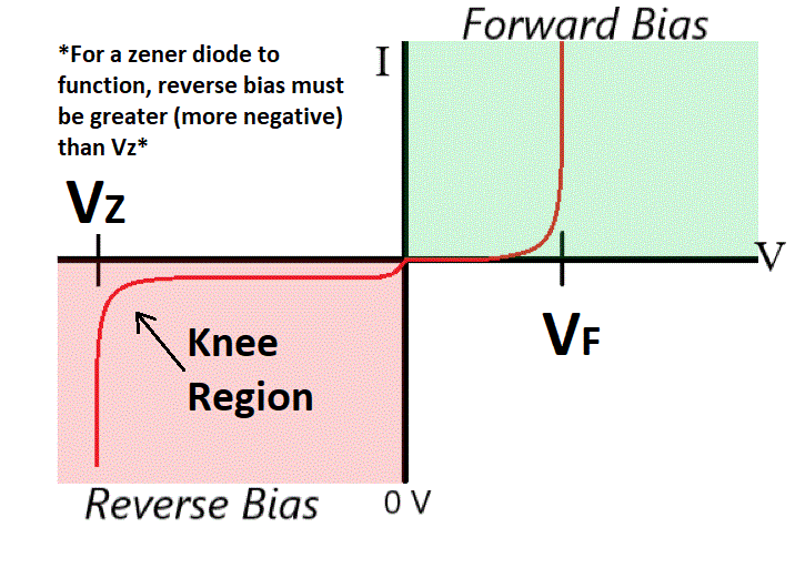
The current-voltage characteristic curve (I-V curve) of a Zener diode resembles that of a conventional diode. The primary difference is that the Zener voltage (VZ) occurs with a much lower negative bias than the breakdown voltage (VB) of a conventional diode.
For the Zener diode to function, the reverse bias applied must be greater than the characteristic Zener voltage (VZ) of the diode. For example, if VZ is -2.5V, a bias of -2.6V will cause the Zener diode to operate correctly.
Zener diodes also exhibit what is called a knee, or a knee region. If a negative bias less than, but close to, VZ is applied, current may be still allowed to flow through the Zener diode. However the Zener diode will not function normally; instead of the voltage being stable with a varying current, the voltage will be strongly dependent on the applied current.
If a forward bias is applied, a Zener diode will function like a conventional diode, allowing current to pass as long as the forward bias is greater than the threshold voltage VF.
Zener Breakdown
Zener diodes operate due to the principle of Zener Breakdown. When a P-N junction is made to be narrow, a sufficient voltage can cause electrons to tunnel through the depletion region, to the opposite side of the junction. Tunneling is a quantum mechanical phenomenon that occurs because the electron has wave-particle duality. In quantum mechanics, electrons are modeled to be wave functions rather than simple ‘particles’. They are spread out in space, with a probability of being at a certain point. Due to this probabilistic nature, if a barrier (like the depletion region) is made small enough, there is a probability that the electron can tunnel through the barrier to the other side.
This is how Zener breakdown occurs; given enough energy by the electric potential, the chances of an electron tunneling through the barrier increases dramatically.
Avalanche Breakdown
In contrast with Zener breakdown, avalanche breakdown occurs at a significantly greater reverse bias and relies on a different principle of operation.
During avalanche breakdown, free electrons and holes are excited to such high levels that they collide with other free electrons and holes, accelerating them across the depletion region. This is analogous to high velocity snow colliding with snow sitting on a slope and creating an avalanche down a mountain.
Zener vs. Avalanche Breakdown
Zener diodes often rely on avalanche breakdown when a high enough reverse bias is applied. In most cases, breakdown below a reverse bias of 5 volts is caused by Zener breakdown. With reverse bias above 5 volts, the dominant mode is typically avalanche breakdown.
Effect of Temperature on Zener Diodes
Zener breakdown exhibits a negative temperature coefficient; as temperature increases, the Zener voltage decreases. A lower reverse bias is required to generate current through the diode. This is due to the thermal energy of the electrons at higher temperatures. The thermal energy increases the total energy of the electrons, enabling them to tunnel more easily through the depletion region.
On the other hand, avalanche breakdown exhibits a positive temperature coefficient. When the temperature increases, the vibration of electrons, holes, and atoms increases. This decreases the average length of travel of electrons and holes, also known as their mean free path. They collide with more obstacles on their way to the junction, which means that they are less likely to accelerate free electrons or holes through the junction. Thus a higher temperature increases the avalanche breakdown voltage.
These two effects tend to cancel each other out, making Zener diodes more reliable across a wider range of temperatures.