Electrical Nodes and Junctions
- A node consists of the point where the terminals of two or more circuit elements meet and any wires/conductors between the terminals.
- Everyone agrees on the definition of a node.
- A junction is most commonly defined as any point in a circuit where current splits.
- Junctions are also sometimes defined as a node connecting three or more circuit elements.
Electrical Node:
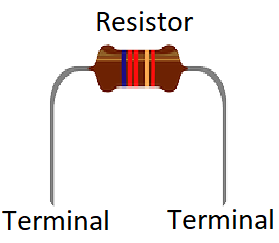
An electrical node is a point in a circuit where two or more circuit elements meet. An element can be a resistor, a capacitor, transistor etc. Each element has conductors that extend from the body of the element itself called terminals. Terminals allow the element to connect into the circuit. The conductors that allow the element to connect to the circuit are called terminals.
Technically, a node is where the terminals of two elements meet.
However, if there are wires in between the terminals, then the wires themselves are also part of the node. Nodes are sometimes defined as the entire span of the circuit having no difference in voltage (i.e. no resistance).
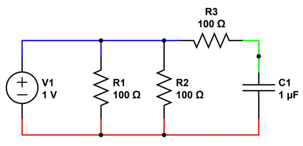
In the circuit above, there are three nodes at the connections between the elements:
- The first node (in blue) is between the terminals of the DC voltage source V1, and resistors R1, R2, and R3. Note that the terminals themselves are not technically part of the node, so they are in black.
- The second node (in green) is between the terminals of resistor R3 and capacitor C1.
- The third node (in red) is between the terminals of the DC voltage source V1, resistors R1 and R2, and capacitor C1.
Electrical Junction:
Here’s where things get tricky. Physics (scientists) and engineering (engineers) sometimes have slightly different definitions of the term electrical junction.
Physics (scientists): A junction is any point in a circuit where a current can split. Unlike nodes, junctions are points. Junctions do not include the wires of equal potential around the junction (whereas nodes are both the point of connection and any connecting wires between terminals). In fact, they can also be the connecting points between elements and wires. Anywhere the current can split. In the circuit above, the black dots are junctions. The circuit has three (3) nodes but five (5) junctions. This is the definition of a junction that you’ll find in most textbooks.
Engineering (engineers): Sometimes agree with the scientists and sometimes don’t. Engineers occasionally redefine things to make it easier for them to work. When they don’t agree with physicists, engineers often say that a junction IS a type of node that has at least three connecting elements. In this definition, a junction is a type of a node. A node has at least two connecting elements, but a junction has at least three connecting elements. However, engineers sometimes exclude the connecting wires when defining junctions in this way. Sometimes engineers define both nodes and junctions as points (rather than the whole interconnecting wire).
Nodes vs. Junctions: Does it really matter?
Usually, the distinction between nodes and junctions doesn’t matter much. They both represent connections between circuit elements. If you ask for voltage difference between two nodes or junctions, you will obtain the same answer unless they are talking about two junctions within the same node. In this case the voltage would be zero and it’s a trick question or mistake.
When a distinction does matter, you can quickly figure out what the other person (or book) is talking about specifically. Most of the time, scientists and engineers want to be as specific about things as possible. They will usually phrase a question by identifying specific points or elements, like the ‘Junction at Point A’, or the ‘Node between R1 and R3’, so you can easily figure out what they are talking about specifically.
When is it better to use nodes?
Any time you are analyzing a circuit based on conservation through multiple current paths.
It is usually safer and easier to use nodes than junctions when doing using Kirchoff’s Current Law (KCL). If you use junctions, you may have to break up the circuit into smaller pieces. You’ll end up working harder for the same result. For instance, in a parallel circuit like the one above, you could use KCL to analyze each junction but you’ll end up using an extra two equations (one for each junction of the first two current branches). Then you’ll have to solve for each unknown current. You’ll have more equations but an equal number of additional unknowns. It just makes your life harder. KCL is also called the nodal rule for a reason.
When is it better to use junctions?
Any time you are analyzing a loop, such as when using Kirchoff’s Voltage Law (KVL). Using the junctions as the corners when possible, you can easily define the boundaries of the loop. This makes it easy to set up the KVL equations without confusion.