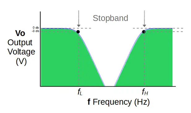
The band stop filter is a type of filter circuit that is used to attenuate frequencies above and below a designated band of frequencies called a stopband.
This page contains a series of calculators to aid in the design of band stop filter circuits.
A band stop filter consists of a high pass filter and low pass filter connected together in parallel.
They contain four basic components that are used to determine the stopband: two resistors R1 and R2, and two capacitors C1 and C2.
Band Stop Filter Circuit
Band stop filters attenuate a stopband that is determined by two characteristic frequencies: the low cut-off frequency FL and the high cut-off frequency FH. This is similar to a band pass filter, and is essentially exactly the opposite. These characteristic frequencies are determined by the values of the components used.
The components of the low-pass filter stage, C1 and R1, determine the value of the low cut-off frequency FL.
The components of the high-pass filter stage, C2 and R2, determine the value of the high cut-off frequency FH.
This page contains a series of calculators to help you design and understand the band stop filter circuit.
It features calculators for the characteristic cut-off frequencies, values of the capacitors and resistors, and a resonant frequency calculator.
Band Stop Filter Cut-Off Frequency Calculator
The band stop filter cut-off frequency calculator can be used to calculate the cut-off frequencies of the filter. Two inputs are required for each cut-off frequency.
Calculation of the low cut-off frequency FL requires (1) the resistance of R1, and (2) the capacitance of C1.
Calculation of the high cut-off frequency FH requires (1) the resistance of R2, and (2) the capacitance of C2.
Based on these values, the calculator will provide the cut-off frequency as well as the resonant frequency of the filter.
The following equations determine FL and FH in the band stop filter:
f_L = \frac{1}{2 \pi R_1 C_1}f_H = \frac{1}{2 \pi R_2 C_2}Band Stop Filter Capacitor Selection Calculator
The band stop filter capacitor calculator can be used to calculate the values of capacitors needed to create a filter with a specific cut-off frequencies FL and FH.
Calculation of each capacitor value requires two inputs. C1 requires the low cut-off frequency FL and the resistance of R1. C2 requires the high cut-off frequency FH and the resistance of R2.
The following equations determine C1 and C2 in the band-stop filter:
C_1 = \frac{1}{2 \pi R_1 F_L}C_2 = \frac{1}{2 \pi R_2 F_H}Band Stop Filter Resistor Selection Calculator
The band stop filter resistor calculator can be used to calculate the values of resistors needed to create a filter with a specific cut-off frequencies FL and FH.
Calculation of each resistor value requires two inputs. R1 requires the low cut-off frequency FL and the capacitance of C1. R2 requires the high cut-off frequency FH and the capacitance of C2.
The following equations determine R1 and R2 in the band-stop filter:
R_1 = \frac{1}{2 \pi C_1 F_L}R_2 = \frac{1}{2 \pi C_2 F_H}Band Stop Filter Resonant Frequency Calculator
The band stop filter resonant frequency calculator can be used to determine the resonant, or center, frequency of a filter with cut-off frequencies FL and FH.
Calculation of the resonant frequencies requires both the low cut-off frequency FL and high cut-off frequency FH.
If these calculators didn’t help, check out our other calculators for electronics or our comprehensive tutorials!