Potentiometer
Have you ever turned a dimmer switch to control the brightness of a light or the speed of a fan? Have you ever wondered how it works? Well, that’s only possible because of the potentiometer.
One of Thomas Edison’s most significant inventions of 1872, the potentiometer, is still commonly used industrially and domestically.
This article will inform you about what you should know about potentiometers. However, before everything else, we must first understand what a potentiometer is.
What is a Potentiometer?
A potentiometer, often called ‘pot’, is a three-terminal resistor that controls the flow of electric current. It consists of a slider or knob that can rotate and change the resistance of the potentiometer. In simple terms, a potentiometer is a variable resistor that can alter the amount of current that follows in a circuit.
Potentiometers were originally based on a type of voltage-measuring instrument (voltmeter). Another word for voltage is ‘electric potential’, which is how the potentiometer came to have its’ name. The original potentiometers measured voltage by functioning as voltage dividers, and modern potentiometers have the same function.
They are popular both in industrial and consumer applications, and are commonly found in household appliances such as volume control or light dimmers.
Now that we understand what a potentiometer is, we can learn how they work by seeing how they are constructed.
Potentiometer Construction
A potentiometer consists of five parts: terminals, resistor, wiper, shaft, and wires. The body of the potentiometer is made from a resistive material (the material types are discussed later in the article). The resistive material is either flat or angled, depending on the movement of the wiper.
In the image below, A) is the shaft that is used to turn C) the wiper. B) is a stationary resistive element, and D) is the underside of the shaft (A). E) and G) are terminal end connected to either end of the resistive element, and F) is the terminal connected to the wiper. H) is a mechanical stop.
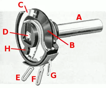
A, D) Shaft
B) Stationary (non-sliding) resistive element
C) Wiper (connected to the shaft)
E, G) End terminals
F) Wiper terminal
The potentiometer is made of two assemblies that comprise sliding and non-sliding parts. The sliding part contains the wiper, and the wiper can either move rotationally or translatory.
The two ends of the resistive material are connected to two of the three terminals. The maximum resistance is measured between these two terminals. The third terminal is connected to the wiper (sliding part). The wiper terminal will measure a variable resistance that is determined by the position of the wiper, which is controlled by the shaft. It is the wiper terminal that is responsible for the variable resistance of the potentiometer.
Materials Used to Make Potentiometers
The materials used to make the resistive material body of a potentiometer includes carbon particles in graphite, conductive plastic, and cermet.
Graphite (carbon particles) are the most common material used, and the first potentiometer invented by Thomas Edison also used carbon. Graphite is affordable and has the desired characteristics required by a potentiometer. Carbon is also used to produce carbon film and carbon composition resistors.
Conductive plastic is not as durable and long-lasting as carbon but can run through many cycles before they need to be replaced. They are most commonly used in high-end types of equipment and have a high resolution and low noise level. However, conductive plastic is costly and unsuitable for household appliances.
Cermet is a material made of a combination of a ceramic and a metal. The goal of cermet resistors is to combine the benefits from both types of materials. Cermet is a common material for resistors, and standard (non-potentiometer) cermet resistors are widely produced. They can handle extreme temperatures, but they are expensive and not very durable, only lasting a few cycles.
When to Use a Potentiometer?
As mentioned before, a potentiometer is used to adjust the current in electrical devices. They are most commonly used to control audio equipment volume, brightness, and many other purposes. The different uses of potentiometers are listed below:
- Controlling the loudness of audio equipment.
- Altering the brightness of lights or device screens.
- Used in hand controllers and joysticks.
- Used in Medical Beds
- Used as position feedback devices (servomechanisms) to create a closed-loop control.
- Used in transducers to produce large output signals.
- Used as Voltage dividers
Potentiometer Symbol
There are a few symbols for potentiometers in use, and these can vary based on whether it is pre-set or
According to the International Electrotechnical Commission (IEC), the symbol of a potentiometer depicts a rectangle between two straight lines. According to the American National Standards Institute, the symbol of a potentiometer depicts two straight lines with a zigzag pattern in the middle.
How Does a Potentiometer Work?
The resistance of a potentiometer is adjusted using a movable wiper connected to a resistive material; as the wiper moves from one terminal to the other, the resistance increases. Potentiometers do not require a power supply or additional circuits.
The principle of working of the potentiometer is based on the principle that the electric potential across the wire is directly proportional to the length of the wire as long as the cross-sectional area remains uniform. This principle can be depicted in the formula:
V = IR and
V is the voltage, I is the circuit’s current, and R is the total resistance. Using this formula, we can write:
R = ρL/A as V = I (ρL/A)
Where ρ is the resistivity of the wire, L is the length of the wire, and A is the cross-sectional area of the wire.
Potentiometer vs. Rheostat
A potentiometer can also be used as a rheostat. A rheostat is a variable resistor that can control the current with two connections and is commonly used for calibrating or tuning circuits. Only two pins are needed to use a potentiometer as a rheostat.
While a potentiometer uses all three terminals (two connected to a resistive element and the third connected to the adjustable wiper), a rheostat only uses two of these three terminals (one connected to a resistive element and the second connected to the adjustable wiper).
In a potentiometer, the more you turn the right (clockwise), the greater the resistance. In a rheostat, the more you turn it to the right (clockwise), the lesser the resistance. So, while a potentiometer gives variable voltage by moving the wiper, a rheostat will give variable resistance by moving the wiper.
Potentiometer Wiring
Wiring a potentiometer does not require a professional and is a straightforward task. To wire a potentiometer, you will need to orient the first terminal toward ground (the side that you want to exhibit lower electric potential), provide the primary input to the second terminal and use the third terminal as the variable ourput. To wire a potentiometer, follow these steps:
Step 1: Prepare the Potentiometer
The first thing you need to do is to choose a potentiometer. Read the resistance printed on the potentiometer and note the most resistance it can provide. The higher the resistance range, the more you can control the appliance. A typical potentiometer is a 100K potentiometer, meaning it can provide a resistance of up to one hundred thousand ohms.
Then, set the potentiometer onto a flat surface with the three terminals facing you. Now, identify the main terminals that are sticking out of the potentiometer. The first terminal is the terminal on the left and is the ground, the second terminal is the terminal in the middle and is the input signal, and the third terminal is the terminal on the right and is the output signal.
Next, measure the wire that needs to be soldered onto the terminals and strip the insulating layer using wire cutters.
Step 2: Soldering the Terminals
You can use any soldering wire except for acid-core wires, mainly for plumbing and not electronics. First, connect the ground wire to the first terminal on the left. Place the wire onto the terminal and tap it with the soldering iron. Then, solder the output wire of the device to the second terminal in the middle in the same way.
You can solder the input to the third terminal and the output to the second terminal. But that means you must turn the knob clockwise to turn the signal down.
Finally, connect the input wire to the third terminal on the right.
Step 3: Check the Potentiometer
Test the potentiometer with a voltmeter. Connect the voltmeter terminals to the input and output of the potentiometer and turn the knob on the potentiometer. The potentiometer works if the voltage reading goes up and down as you turn the knob.
Once you’ve tested the potentiometer, connect it to the appliance or device you want. Cover the knob, and you’re done.
Types of Potentiometers
There are different types of potentiometers in the market, and although they have the same working principle, they have their differences. The different types of potentiometers are listed below:
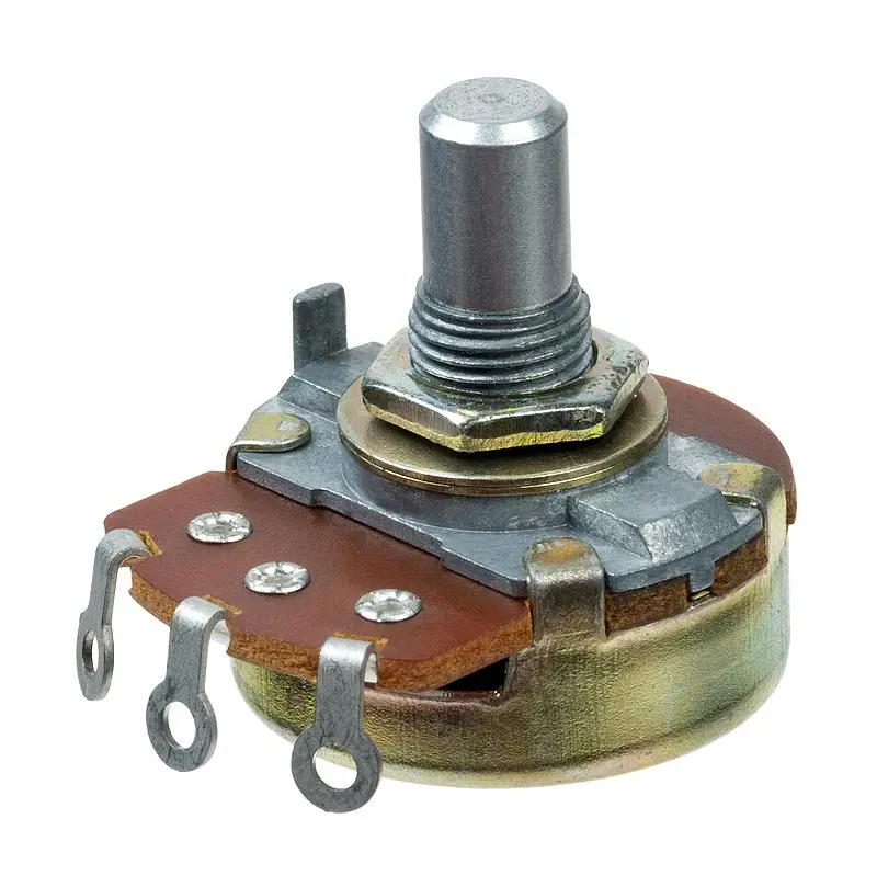
Rotary Potentiometers
Rotary potentiometers are the most common types of potentiometers used. They consist of an adjustable wiper that moves in a circular motion when turning the knob. They are primarily used to obtain an adjustable supply of voltage.
The resistive material is placed in a semi-circular pattern between the two terminals. The rotary potentiometers are divided into five types:
- Single-Turn potentiometer: only rotate three-fourths of a complete turn (270°)
- Multi-Turn Potentiometers: provide multiple rotations and are more precise.
- Dual-Gang Potentiometers: consists of two potentiometers connected on the same shaft. They allow controlling two different channels simultaneously.
- Concentric Potentiometers: consist of two potentiometers connected individually to the shaft.
- Servo Potentiometers: consist of motorized potentiometers that can automatically adjust the voltage supplied.
Linear Potentiometers
Liner potentiometers, also called slider or fader potentiometers, consist of an adjustable wiper that moves in a linear motion. Linear potentiometers are commonly used to measure the resistance of voltage.
The resistive material is attached to a track alongside which the wiper moves. Linear potentiometers are further divided into four types:
- Slide Potentiometer: consists of a single linear swiper.
- Multi-Turn Slide Potentiometer: consists of a spindle that allows multiple rotations and provides increased precision.
- Dual-Slide Potentiometer: consists of a single wiper that controls two potentiometers simultaneously.
- Motorized Fader Potentiometer: consists of an automatically adjusted wiper controlled by a servo motor.
Digital Potentiometers
Digital potentiometers are gaining popularity in the technologically advanced age. They are controlled electronic components with similar workings as a standard potentiometer. The resistance of the potentiometer is adjusted through digital input signals. They are most commonly used in factory equipment that requires increased precision.
Digital potentiometers are popular due to their high precision, small size, durability, and reliability.
Potentiometer Taper
Taper is one of the main concepts associated with a potentiometer and shows the relationship between the resistance of the potentiometer and the Knob position of the potentiometer. Taper is divided into two main types: linear tapers and logarithmic tapers.
Linear Taper Potentiometers
Linear tapers are the most common type of potentiometers. In a linear taper, the relationship between the Knob position is directly proportional to the resistance of the potentiometer. The resistance increases as the knob is turned (and the wiper is moved along the track). If the knob is in the medium position, the output voltage will be half the total.
Potentiometers with a linear taper are marked with a B on them. For example, a 10K potentiometer will have “B10K” marked on it.
Logarithmic Taper Potentiometers
Logarithmic tapers are specially used potentiometers most commonly found in audio control applications. In a logarithmic taper, the relationship between the Knob position is non-proportional to the resistance of the potentiometer. This means that the resistance change varies with the wiper’s position. The change in resistance at one end of the track is greater than at the other.
Logarithmic tapers can be log tapers or inverse log tapers. In log tapers, the change in resistance increases as the wiper moves along the track. In an inverse log taper, the change in resistance decreases as the wiper moves along the track.
Potentiometers with a logarithmic taper are marked with an A on them. For example, a 10K potentiometer will have “A10K” marked on it.
Advantages and Disadvantages of Potentiometers
Potentiometers are one of the well-known devices in the electronic industry but are they the best option? Here are some advantages and disadvantages of potentiometers:
Advantages
- They have a simple construction and are easy to connect.
- They are low-cost devices.
- They are easy to use.
- It offers a wide range of resistance values.
- They are highly efficient and precise. They work on a zero deflection method, which means that an error is possible.
- It is a proven technology that has been used for decades.
- It can measure small electromotive forces.
- It has a wide range of applications.
- It does not need a voltage input to work.
- It is durable and has a long life span. Most potentiometers can operate for up to fifty thousand cycles.
- It provides low noise and enhanced performance.
Disadvantages
- Its operation is slow.
- It has limited bandwidth.
- Linear potentiometers require a larger force on the wiper.
- Accuracy decreases due to external factors such as water and dust.
- The sliding of the wiper can cause friction.
- It is challenging to keep the temperature of the potentiometer uniform, and it can over-heat.
Alternates to The Potentiometer
Although they have many advantages, we have seen that potentiometers also have some flaws. One alternative to the potentiometer is the Magnetic encoder module.
The magnetic encoder is a type of rotary encoder. It consists of three components: The sensor, the rotating wheel, and a series of magnetic poles.
The encoders provide a rising voltage output using a three-wire system. They have an unlimited life and are not prone to wear and tear. They are not affected by outside temperatures or other environmental factors.
Magnetic encoders can provide a linear output voltage without any physical contact. They can also be sealed for underwater operations and are safe from contamination such as dirt, oil, grease, dust, etc.
Potentiometers – In Conclusion
A potentiometer is a commonly used technological device in the electronic industry and has many applications. The potentiometer is such a helpful device that it has been used for decades and will continue to be used as we invent more technologies.
Although they have some disadvantages, their advantages far outweigh them. When installing a potentiometer or making a potentiometer, ensure all safety checks and only do it if you fully understand what you are supposed to.
Now that you know what a potentiometer is and how it works, you can put it to use.