Resistors Capacitors and Inductors
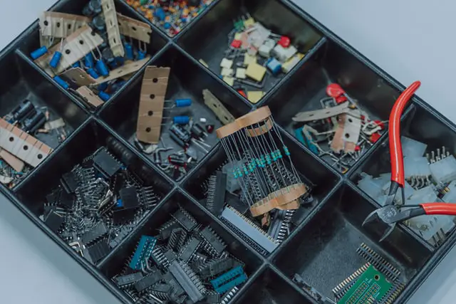
Resistors, capacitors, and inductors are the three fundamental passive circuit elements used in electric circuits. Together, they constitute the three fundamental building blocks of classical electrical engineering.
Resistors are components that resist the flow of electric current. This allows us to control the current in circuits as well as do many other useful things. A resistor is just an imperfect conductor, and you can make a resistor just by using a really long wire (as wires themselves have some resistance). Resistors are used in virtually every circuit. A few examples are voltage dividers, filters, and biased active circuits.
Capacitors store and release electric charge (kind of like a battery). Their properties are different in DC vs. AC circuits but can be useful in both. Capacitors are commonly used to stabilize voltage, to block DC, to improve filters, and to tune resonant circuits. As with resistors, it is difficult to find an electronic product that doesn’t use capacitors.
Inductors also store energy (like capacitors). But they do it in a very different way: by storing it in a magnetic field. An inductor can be made just by coiling a wire. In circuits, inductors often have effects that complement the effects of capacitors. Like capacitors, they are also used in filter circuits and tuned circuits. A transformer can be thought of as two paired inductors.
| Resistor | Capacitor | Inductor | |
| Quantity | Resistance (R) | Capacitance (C) | Inductance (I) |
| Unit | Ohm (Ω) | Farad (F) | Henry (H) |
When combined with active elements like voltage sources and transistors, as well as passive semiconductor elements like diodes, you can build almost anything within the realm of electronics.
The study of resistors, capacitors and inductors allows us to gain a deeper intuition of some of the most important principles that affect the design and operation every circuit.
This is because every circuit has resistance, capacitance, and inductance even if they don’t contain resistors, capacitors, or inductors.
For example, even a simple conducting wire has some amount of resistance, capacitance, and inductance that all depend on the material composition, gauge (i.e. thickness), construction, and shape.
Before we do a deep dive on each component type, let’s gain an understanding of how different components come together to make electronics work.
Resistors
Resistors are used to reduce and control the flow of electric current.
They are basically inefficient conductors that convert electrical energy into heat. This may seem wasteful, but resistors are immensely useful in producing needed voltages and/or currents.
Like using a carving chisel to remove material to uncover a desired sculpture, a resistor circuit can be used to take any incoming signal and reduce it to whatever network of voltages and/or currents needed.
A great example of this is a voltage divider circuit, where a series of resistors are used to provide ‘taps’ at different voltage levels.
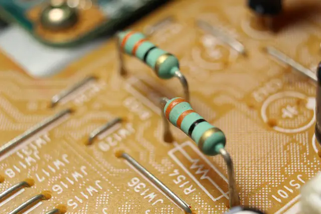
Two resistors on a PCB (printed circuit board).
In controlling a voltage or current, resistors always follow Ohm’s Law. This means that the current and voltage ‘drop’ are interdependent; if a precise reference voltage is required, then the current must also be controlled precisely.
Capacitors
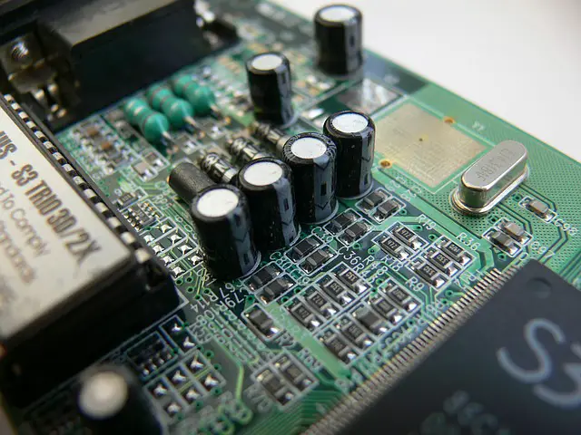
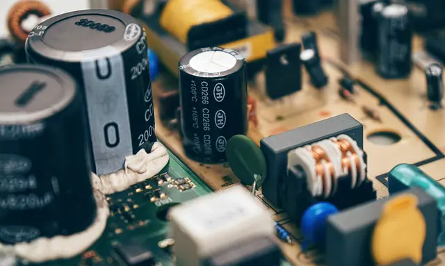
This circuit contains six (6) electrolytic capacitors.
Capacitors store electrical energy, somewhat like rechargeable batteries. Unlike batteries, they tend to have a lower capacity to store charge and also discharge very quickly.
In a capacitor, energy is stored by polarizing a dielectric (insulating) material. As energy is added to the capacitor, more charge separation occurs in the dielectric material itself. Unless a high enough voltage is placed on the capacitor such that it is damaged, charge separation and release has virtually no impact on the dielectric material itself. This makes a capacitor extremely reliable; capacitors that are many decades old often still function perfectly.
Capacitance in a simple conductor, like a wire, can become significant when there is another conductor (like another wire, or a person, or the earth) nearby.
Capacitors don’t allow current to pass directly through them, so they can be used to filter out DC signals.
DC current only ‘flows through’ a capacitor while the capacitor is charging or discharging. They can also smooth out signals by releasing their charge when needed, which is very useful for creating smooth voltage waveforms in circuits like rectifiers.
Inductors
Inductors also store energy but in a much different way than capacitors.
An inductor stores energy in a magnetic field. Every current carrying conductor generates a magnetic field, which can be intensified simply by coiling the wire. This is a simple example of an inductor.
The magnetic field around the conductor is sensitive to any change in current, and it automatically produces a voltage that opposes any change in current. For this reason, inductors are great at ‘smoothing’ out electric signals.
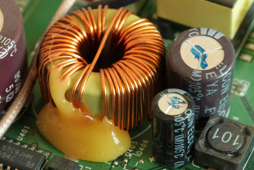
Inductors are also often used to filter out alternating current (AC) signals, because an AC signal, by definition has a constantly changing current. When an inductor is exposed to AC, it will produce a voltage that opposes the change in current.
Inductors can also be used to filter different frequencies and to make tuned circuits, which are very useful in radio and television.
Developing Intuition Using Resistors, Capacitors, and Inductors
Resistors, capacitors, and inductors are not only classic building blocks of circuits. They inform us about the nature of the properties of resistance, capacitance, and inductance. Even a bare wire has some resistance, some capacitance, and some inductance. Every change made to a circuit including the length of wire, the type of resistor, the physical size of the capacitor, how closely wires are spaced, etc. has some impact on these qualities.
Depending on the system, the resistive, capacitive, or inductive properties of simple conductors can have a dominating effect on the system’s design.
For example, alternating current (AC) systems overtook direct current (DC) systems in the late 19th century due to the resistance of transmission lines. It turns out that power losses due to resistance are very high at low voltages, but DC systems didn’t have a way to increase voltage.
A device known as a transformer was discovered that could increase or decrease the voltage of alternating current (AC), but not direct current (DC). Since resistive losses could be reduced by using a transformer to increase the voltage, AC quickly won out over the competing DC technology. That’s why high voltage AC power lines are used to transmit electrical energy from power plants to our homes and businesses.
However, in small scale circuits the inherent (resistive, capacitive, and inductive) qualities of conducting wires can often be ignored or designed around with ease. Good circuits take them into account, just as they do the tolerances of each component. A circuit designer must understand when each is important and when it isn’t. Luckily, there are often little tricks that substantially help reduce the difficulty of a real life problem.
When learning about these three components, try to learn the basic rules and develop an intuition for them. What happens to resistors in series and parallel teaches us something about the nature of resistance. But what happens when you put a really big resistor in parallel with a small one? You might be able to just ignore the big one.
In another example of developing overall intuition by learning about resistors, learning about voltage dividers is important. What’s more important is learning how resistors in series affect any signals (voltage readings) taken from between the resistors. You can develop an intuition for approximately what a voltage is (compared to ground) where the circuit branches off in between stacks of resistors.
Combinations of RCL Elements
We’ll quickly learn about each component type in series and parallel. What happens when you combine them? RC (resistor-capacitor), RL (resistor-inductor), LC (inductor-capacitor), and RCL circuits can be thought of as circuit ‘Lego’ blocks. By putting them together and understanding the combinations, we get closer to becoming intuitive circuit builders. These circuits are also useful as filters which can be tuned by changing the value of their elements.
Circuit Elements vs. Circuit Components
Circuit elements, or components, are what electrical circuits are made of, along with any conductive interconnections between them.
| Circuit Components | Circuit Elements |
| Real | Abstract |
| Imperfect | Ideal |
| Independent of circuit | Only referenced while in circuit |
Technically the individual devices are known as components on their own, and as elements when we are talking about their place in a circuit.
Often these terms are used interchangeably. However, the term circuit element always refers to an abstract version of the component.
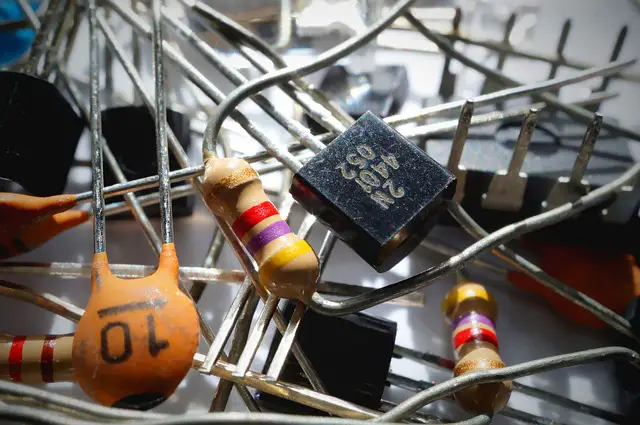
These components can be connected together to form a circuit. Can you spot the transistor?
The exceptions are voltage and current sources, which are always referred to as elements (not components).
Circuit elements are idealized, abstract concepts that represent the real components that electric circuits are constructed of. On paper, we represent elements as being perfect and we calculate things like voltage and current based on that assumption.

The pi filter above uses two capacitors (C1 and C2) and an inductor (L1) to help produce a high quality signal in a power supply. Rb is a bleeder resistor used to safely discharge the capacitors. Similar circuits are used in most power supplies, like the adapter for your computer or cell phone.
But real-life circuit components are not perfect; they have tolerances and non-linear behavior. For example, a resistor comes with a tolerance of +-x% which helps to account for any issues with quality control. Every single component has tolerances, so there is often no point in calculating values to a high number of significant figures.
Instead, circuit designers engineer their circuits with a range of tolerances in mind. One sign of a well-designed circuit is that it can handle all of the expected tolerances in all of its components and still function well.
Some amount of pen-and-paper computation is helpful in learning to understand circuits and electronics. After a while, you’ll learn to calculate things roughly: in your head or on a napkin, using approximations. Being able to do this is much more important than being able to analyze a really weird circuit to high degree of precision.
Types of Circuit Elements
Circuit elements can divided into three categories: passive, active, and electromechanical.
Passive Circuit Elements
Passive components include resistors, capacitors, inductors, and even diodes. A passive component is one that does not supply energy to the circuit.
Active Circuit Elements
Active components include voltage sources, current sources, and amplifiers such as transistors and vacuum tubes. An active component supplies energy.
Electromechanical Circuit Elements
Electromechanical components translate electrical signals into mechanical motion or vice versa. Motors and generators are common examples. Another, more recent example is that of MEMS, microelectromechanical systems. MEMS are tiny electromechanical devices that are made using nanoscale semiconductor technology.
We’ll explore each of these components throughout this course beginning with resistors, capacitors, and inductors in this Module.
Let’s explore resistors in depth, in Lesson 5: Resistors in Series.
Module 3 – DC Circuits
Lesson 15: Inductors